B Torque Calculation - Not a basic application

  • B
  • Thread starter Thread starter TeeBeeCee
  • Start date Start date
AI Thread Summary
The discussion revolves around calculating the torque delivered by a hydraulic machine used for tightening bolts and nuts. The hydraulic ram, with a 4-inch diameter piston generating 100 PSI, applies force to a cog, and the torque is influenced by the angle at which the ram engages the cog. The torque formula T = F x r x sin(theta) is highlighted, emphasizing that both the radius (r) and angle (theta) change during operation, affecting the torque output. Accurate measurements of the stroke length and angles are crucial for precise torque calculations. The goal is to tighten bolts to specific torque specifications by adjusting hydraulic pressure accordingly.
TeeBeeCee
Messages
15
Reaction score
4
TL;DR Summary
How to calculate torque on a rotating gear driven by a hydraulic ram.
Please disregard this post if this forum is only academia related. This is a real word physics question.

I work in a hydraulic cylinder repair shop. I have a hydraulic machine that can tighten and loosen bolts and nuts with a lot of torque. When tightening, it is important to know how many foot/pounds of torque was used.

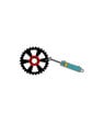
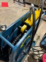
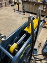
Here is how the machine works. A hydraulic ram pushes on the circumference of a cog that has a socket in the center. The hydraulic ram has a 4” diameter piston. So the surface area of the piston is about 13 square inches.

Assuming the ram is pushed with 100 PSI of force, what is the torque delivered to the socket? Does the cog provide additional torque, similar to a lever? Does the angle of the ram engaging with the cog affect the torque? What additional information do you need to provide an accurate answer?

Here is a crude diagram pieced together from clip art. Hopefully it helps to illustrate the problem.
 

Attachments

  • Torque Problem.jpg
    Torque Problem.jpg
    9.1 KB · Views: 30
Physics news on Phys.org
Welcome, TBC!

Do you have a way to use a torque instrument?

Assuming the pressure will not be good, you will need to measure it.
The torque on the nut or bolt will be greater as the distance between the shaft and the center line of the cylinder increases.

Please, see:
https://www.grc.nasa.gov/www/k-12/airplane/torque.html

ratchetdiagram.gif
 
Building on variables needed to calculate a precise answer, the ram has a maximum stroke length, and as it extends to push the gear, the angle will change as the end of the gears travels in an arc per X degrees of gear rotation. What about the other components of the question? What other information is needed? I was hoping for a formula.
 
TeeBeeCee said:
Building on variables needed to calculate a precise answer, the ram has a maximum stroke length, and as it extends to push the gear, the angle will change as the end of the gears travels in an arc per X degrees of gear rotation. What about the other components of the question? What other information is needed? I was hoping for a formula.
The problem you have is that the required torque is reached at whatever angle the specific bolt or nut assembly reaches maximum clamping force.

As the torque induced by your ram is dependent on that angle (nut and gear), which is different for each case, you will have different values of maximum torque for each case.

If it happens that the center line of the ram is perpendicular to the line joining center of gear and the point at which gear and ram connect, when tightening, you will know how that the maximum foot/pounds of torque (for that pressure) was used.

If not, you will need to know the last angle that the gear reached for each case in order to precisely do the calculation.
 
Lnewqban said:
Welcome, TBC!

Do you have a way to use a torque instrument?

Assuming the pressure will not be good, you will need to measure it.
The torque on the nut or bolt will be greater as the distance between the shaft and the center line of the cylinder increases.

Please, see:
https://www.grc.nasa.gov/www/k-12/airplane/torque.html

:cool:
No instrument to measure the torque. Isn’t pressure just one of the variables needed? In the example, 100 PSI of hydraulic pressure is applied to a piston area of 13 square inches, which will develop 1,300 ft pounds of force. In the formula T = F x r x sin(theta), it looks like to me like r will change and definitely theta. I ‘m getting hung up on push/pull versus rotational force. We also have the question about the metal cog that is part of the system. Does it have an impact?
 
I understand.
Please, study concepts shown in link of post 3 above, and come back with more questions.
 
The triangle I have drawn in here is going to a piece of the puzzle. Can you relate all the variables using trigonometry "Law of Cosines"?

1742477056974.png

After you get the relationship, there are a few trig identities to apply to find the torque as a function of ##x##. I'll explain the relevant stuff with forces/torques you need to understand along the way.

Keep in mind...I don't know what level of math you are comfortable with... but a "precise" mathematical model requires some knowledge. If you are looking for conceptual, we can help with that too.

If you show honest engagement but can't do the math, I'll give you a formula in the end to play around with.
 
Last edited:
TeeBeeCee said:
We also have the question about the metal cog that is part of the system. Does it have an impact?
Why does the machine have a gear if it is not meshing to another one?
Could you take one or two pictures of the machine for us to see?
How much is the stroke of the ram and the center to pivot radius?
 
  • #10
TeeBeeCee said:
No instrument to measure the torque. Isn’t pressure just one of the variables needed? In the example, 100 PSI of hydraulic pressure is applied to a piston area of 13 square inches, which will develop 1,300 ft pounds of force.
##1300 ~\text{lbf}## ( pound force ) not "ft-pounds" (that's torque).
TeeBeeCee said:
In the formula T = F x r x sin(theta), it looks like to me like r will change and definitely theta. I ‘m getting hung up on push/pull versus rotational force. We also have the question about the metal cog that is part of the system. Does it have an impact?
##r## will not change, ##F## would be a constant in magnitude (for the static, non-accelerating, non moving, rod), ##L## shouldn't change. The angle ##\beta## changes as you suspect, and the total length of the cylinder ##x## changes.
 
  • #11
Lnewqban said:
Why does the machine have a gear if it is not meshing to another one?
Could you take one or two pictures of the machine for us to see?
How much is the stroke of the ram and the center to pivot radius?
The hydraulic ram pushes the gear to generate the rotational force. I will post pictures and measure the stroke tomorrow. For the center to pivot radius, do you mean from the center of the gear to where the end of the ram meets the gear (Post #8 figure, variable r)?
 
  • #12
TeeBeeCee said:
The hydraulic ram pushes the gear to generate the rotational force.
Yes, it was clear in your first posted diagram.
Nevertheless, I would like to know the reason for the teeth (what the gear is meshing with, if anything).

TeeBeeCee said:
I will post pictures and measure the stroke tomorrow.
Please, see if you can picture the mechanism at both extreme positions of the stroke.
That is important to properly help you.

TeeBeeCee said:
For the center to pivot radius, do you mean from the center of the gear to where the end of the ram meets the gear (Post #8 figure, variable r)?
Yes, exactly.
 
  • #13
Lnewqban said:
Yes, it was clear in your first posted diagram.
Nevertheless, I would like to know the reason for the teeth (what the gear is meshing with, if anything).


Please, see if you can picture the mechanism at both extreme positions of the stroke.
That is important to properly help you.


Yes, exactly.
 
  • #14
Here are the pictures and some additional information. The cylinder stroke is 6 inches. It takes 12 strokes to turn the drum 360 degrees, which is 30 degrees per stroke. At the beginning of the stroke the angle of the cog to the gears on the drum is about 6 degrees. At the end of the stroke it is 4 degrees. My goal is to be able to tighten bolts and nuts to a specific torque specification by applying the appropriate PSI of hydraulic pressure. Hopefully this helps.

*NOTE* Images were too big. Working on that.
 

Attachments

  • Exp4.jpeg
    Exp4.jpeg
    61.5 KB · Views: 96
  • Exp4.jpeg
    Exp4.jpeg
    50 KB · Views: 22
  • Exp4.jpeg
    Exp4.jpeg
    50.6 KB · Views: 23
Last edited:
  • Like
Likes Lnewqban and erobz
  • #15
erobz said:
The triangle I have drawn in here is going to a piece of the puzzle. Can you relate all the variables using trigonometry "Law of Cosines"?

View attachment 358757
After you get the relationship, there are a few trig identities to apply to find the torque as a function of ##x##. I'll explain the relevant stuff with forces/torques you need to understand along the way.

Keep in mind...I don't know what level of math you are comfortable with... but a "precise" mathematical model requires some knowledge. If you are looking for conceptual, we can help with that too.

If you show honest engagement but can't do the math, I'll give you a formula in the end to play around with.
It’s been a while since I’ve done any trigonometry. In looking at your annotation, I understand what the variables are. X will change by 6”, the length of the stroke. The angle will also change. When the rod is fully retracted at the beginning of the stroke, the angle is 6 degrees. At the end of the stroke it is 4 degrees, and of course the angle changes slightly during the stroke.
 
Last edited:
  • #16
TeeBeeCee said:
Here are the pictures and some additional information. The cylinder stroke is 6 inches. It takes 12 strokes to turn the drum 360 degrees, which is 30 degrees per stroke. At the beginning of the stroke the angle of the cog to the gears on the drum is about 6 degrees. At the end of the stroke it is 4 degrees. My goal is to be able to tighten bolts and nuts to a specific torque specification by applying the appropriate PSI of hydraulic pressure. Hopefully this helps.

*NOTE* Images were too big. Working on that.
The rod doesn't engage the pawls until its extended about an inch from what I can tell in the picture-5 inch stroke? If you have drawings of the machine that would be better, its going to be challenging to get accurate measurements of the components assembled as far as I can see. We might be able to infer ##L## and ##r## if your angular measurements of 6 and 4 degrees, and stroke are accurate.
 
Last edited:
  • #17
I was thinking the same thing about getting measurements. I don’t have any drawings. I will reach out to the vendor to see if they will send any. In the meantime, I will try to get the best measurements I can. To get the angle of the ram, I used a digital inclination meter.
 
  • #18
erobz said:
The rod doesn't engage the pawls until its extended about an inch from what I can tell in the picture-5 inch stroke? If you have drawings of the machine that would be better, its going to be challenging to get accurate measurements of the components assembled as far as I can see. We might be able to infer ##L## and ##r## if your angular measurements of 6 and 4 degrees, and stroke are accurate.
From the diagram with the triangle, where is the torque variable? What is the formula to determine the torque given the variables listed?
 
  • #19
TeeBeeCee said:
From the diagram with the triangle, where is the torque variable? What is the formula to determine the torque given the variables listed?
You have to find the cosine of the angle ##\beta## as a function of ##x##, then the torque ends up being ##\tau = rF\sin\beta##
 
  • #20
Is that chain linked to the hydraulic motor?
If so, what those two do?
 
  • #21
Lnewqban said:
Is that chain linked to the hydraulic motor?
If so, what those two do?
My guess is that it is a chuck for the nut.
 
  • #22
Lnewqban said:
Is that chain linked to the hydraulic motor?
If so, what those two do?
Yes, once the ram breaks the nut or bolt loose, the hydraulic motor can remove a lot faster (decent rpm). It sacrifices power for speed. It does not play a part in the question.
 
  • #23
erobz said:
You have to find the cosine of the angle ##\beta## as a function of ##x##, then the torque ends up being ##\tau = rF\sin\beta##
It would be very helpful if you provide an example. I really don’t understand the formula you provided.

Let’s say r=16”, beta=6 degrees, I’m lost after that. Sorry, as you can see math is not my strong suit.
 
  • #24
##\beta## isn't 6 degrees, it's going to be more in the vicinity of 90 degrees. ##\beta## is the angle between the force and the radial line from the point of contact to the axis of rotation. It quite literally needs to be the angle in the drawing for the formula to work, not just any of them. The force of the cylinder is ##F## and it's directed along the rod.

But I believe you, so I'm not going to bore you with the details of eliminating it mathematically:

$$ \tau = r F \sqrt{ 1- \frac{(L^2-(r^2+x^2))^2}{4r^2x^2} } $$

having the correct ##r## and ##L## are critical to this, and they will be difficult to measure directly on the assembled machine.

I can do some more algebra, and tell you what they could be ( given some reasonable measurement errors ) if you share what angle measures relative to what are 6 and 4 degrees - relative to what exactly.

This is the torque that is being applied to the nut ( from this mechanism - ideally) when this system is in static equilibrium. Meaning, before the nut breaks loose.

If you are really after the tightening spec, I think it would also be the torque a "torque wrench" should measure if everything was moving very slowly, without jerking and the force was constant from the hydraulic cylinder (measure pressure accurately).

If the torque is critical, what current method are you trying to modify by knowing the torque at the machine?
 
Last edited:
  • #25
erobz said:
##\beta## isn't 6 degrees, it's going to be more in the vicinity of 90 degrees. ##\beta## is the angle between the force and the radial line from the point of contact to the axis of rotation. It quite literally needs to be the angle in the drawing for the formula to work, not just any of them. The force of the cylinder is ##F## and it's directed along the rod.

But I believe you, so I'm not going to bore you with the details of eliminating it mathematically:

$$ \tau = r F \sqrt{ 1- \frac{(L^2-(r^2+x^2))^2}{4r^2x^2} } $$

having the correct ##r## and ##L## are critical to this, and they will be difficult to measure directly on the assembled machine.

I can do some more algebra, and tell you what they could be ( given some reasonable measurement errors ) if you share what angle measures relative to what are 6 and 4 degrees - relative to what exactly.

This is the torque that is being applied to the nut ( from this mechanism - ideally) when this system is in static equilibrium. Meaning, before the nut breaks loose.

If you are really after the tightening spec, I think it would also be the torque a "torque wrench" should measure if everything was moving very slowly, without jerking and the force was constant from the hydraulic cylinder (measure pressure accurately).

If the torque is critical, what current method are you trying to modify by knowing the torque at the machine?
Currently, I use a table of pressure (measured in BAR, not PSI) provided by the vendor of the hydraulic tear down bench. Some torque specs are lower than listed, or are between the values. I need to be able to calculate the amount of hydraulic pressure needed to be able to tighten to any given torque requirement. I have no idea if the information they provided is correct, so I wanted to verify. I’ve included the table below. They use the metric system. Have no idea why the last pressure entry only increased by 15 when all the others were 25.

Table
Pressure (BAR) Torque (NM)
25 4210.87
50 8421.74
75 12632.60
100 16843.47
125 21054.34
150 25265.21
175 29476.07
200 33686.94
225 37897.81
250 42108.68
275 46319.54
300 59530.41
315 53056.93
 
Last edited:
  • #26
TeeBeeCee said:
Currently, I use a table of pressure (measured in BAR, not PSI) provided by the vendor of the hydraulic tear down bench. Some torque specs are lower than listed, or are between the values. I need to be able to calculate the amount of hydraulic pressure needed to be able to tighten to any given torque requirement. I have no idea if the information they provided is correct, so I wanted to verify. I’ve included the table below. They use the metric system. Have no idea why the last pressure entry only increased by 15 when all the others were 25.

Table
Pressure (BAR) Torque (NM)
25 4210.87
50 8421.74
75 12632.60
100 16843.47
125 21054.34
150 25265.21
175 29476.07
200 33686.94
225 37897.81
250 42108.68
275 46319.54
300 59530.41
315 53056.93
Well, if they are giving you table of values they probably tested it. I would stick to the table.

Here is a graph:

1742771794117.png


The wobbly bit at the end is a bit funny, and likely won't be explained by the equation I gave. Thats experimental. Also, excel is "filling in the blanks" with high order polynomials, so you would need some more data out there to be sure about that. The good news is most of the graph seems linear.
 
  • Like
Likes Steve4Physics
  • #27
Steve4Physics said:
Surely the manufacturer must provide a table of pressure vs. torque, so that the operator can look-up the pressure which needs to be set to achieve a particular torque. Or am I missing something?
Yeah, they just posted that.
 
  • #28
erobz said:
Yeah, they just posted that.
I know - just missed it. I deleted my post before I saw that you had replied to it!
 
  • #29
erobz said:
##\beta## isn't 6 degrees, it's going to be more in the vicinity of 90 degrees. ##\beta## is the angle between the force and the radial line from the point of contact to the axis of rotation. It quite literally needs to be the angle in the drawing for the formula to work, not just any of them. The force of the cylinder is ##F## and it's directed along the rod.

But I believe you, so I'm not going to bore you with the details of eliminating it mathematically:

$$ \tau = r F \sqrt{ 1- \frac{(L^2-(r^2+x^2))^2}{4r^2x^2} } $$

having the correct ##r## and ##L## are critical to this, and they will be difficult to measure directly on the assembled machine.

I can do some more algebra, and tell you what they could be ( given some reasonable measurement errors ) if you share what angle measures relative to what are 6 and 4 degrees - relative to what exactly.

This is the torque that is being applied to the nut ( from this mechanism - ideally) when this system is in static equilibrium. Meaning, before the nut breaks loose.

If you are really after the tightening spec, I think it would also be the torque a "torque wrench" should measure if everything was moving very slowly, without jerking and the force was constant from the hydraulic cylinder (measure pressure accurately).

If the torque is critical, what current method are you trying to modify by knowing the torque at the machine?

erobz said:
Well, if they are giving you table of values they probably tested it. I would stick to the table.

Here is a graph:

View attachment 358891

The wobbly bit at the end is a bit funny, and likely won't be explained by the equation I gave. Thats experimental. Also, excel is "filling in the blanks" with high order polynomials, so you would need some more data out there to be sure about that. The good news is most of the graph seems linear.
Was this chart generated from the data table I provided? If so, the point I made was that I have no idea if the data is correct and wanted to verify.
 
  • #30
TeeBeeCee said:
Was this chart generated from the data table I provided?
Yeah, it was. I was trying to help you by giving you a formula for the data so you wouldn't have trouble in between values. Is the value at 300 correct, or a typo?

1742773645529.png


This equation is good for data up to 275 Bar. I just excluded the points at the end. The point at 315 looks like it would fall in line, which is why I asked if the data at 300 was a typo.
 
Last edited:
  • Like
Likes Steve4Physics
  • #31
TeeBeeCee said:
Have no idea why the last pressure entry only increased by 15 when all the others were 25.
I'd guess the maximum operating pressure for the equipment is 315 bar, so the final value in the table is 315 bar rather than 325 bar.
 
  • #32
TeeBeeCee said:
If so, the point I made was that I have no idea if the data is correct and wanted to verify.
Thats fine, but you are going to need precise/accurate measurements of the variables before you can do that. We have to be critical of the model that comes from pure mathematics over what was experimentally measured by the company which designs and manufactures it. There may be "hidden variables" that are difficult to pin down theoretically that would show up experimentally. It's not so easy. Do you suspect a miscalibration, why?
 
  • #33
erobz said:
Thats fine, but you are going to need precise/accurate measurements of the variables before you can do that. We have to be critical of the model that comes from pure mathematics over what was experimentally measured by the company which designs and manufactures it. There may be "hidden variables" that are difficult to pin down theoretically that would show up experimentally. It's not so easy. Do you suspect a miscalibration, why?
I don’t suspect a mis-calibration. It’s just that torque specs are important. A loose bolt or nut can cause severe equipment damage. Just trying to make sure I limit my liability.
 
  • #34
Steve4Physics said:
I'd guess the maximum operating pressure for the equipment is 315 bar, so the final value in the table is 315 bar rather than 325 bar.
Good guess. I just checked and the maximum pressure of the hydraulic pump is 300 bar.
 
  • #35
Regarding that table entry for 300 Bar.
It appears to be a transcription error by whoever supplied the table. The rest of the table is completly linear.

As for the 300 Bar entry, if the "9" is changed to "0", then all the digits match as 3 times the 100 Bar value and 6 times the 50 Bar value.

Except for the last digit, it also matchs as 12 times the 25 Bar value which is likely a round-off error in the 25 Bar value.
 
  • Like
Likes SammyS and Lnewqban
  • #36
Tom.G said:
Regarding that table entry for 300 Bar.
It appears to be a transcription error by whoever supplied the table. The rest of the table is completly linear.
The torque at 300 bar is given as 59530.41 Nm. It appears that the '9' should be a '0', i.e. the value should be 50530.41 Nm.

This puts the 300 bar point exactly on the straight line formed by the other points.

Incidentally (I don't think anyone has said it yet) giving the torque values to 7 significant figures leaves something to be desired!.
 
  • #37
Does anyone else suspect the table not to be actual measured data. It's too perfect (other than the expected typo)?
 
Last edited:
  • #38
erobz said:
Does anyone else suspect the table not to be actual measured data. It's too perfect (other than the expected typo)?
Yes. Almost certainly.

Maybe the values are calculated from the accurately known dimensions (which was what the OP originally wanted to do).

Or maybe the values are based on actual measurements and the best-fit straight line was found. Then the table could be constructed using the gradient of the best-fit line.
 
Back
Top