Discussion Overview
The discussion revolves around understanding a specific circuit involving relays controlled by a microcontroller. Participants are exploring the purpose of the circuit, its application in phase voltage measurement, and the calculations related to voltage at the microcontroller input.
Discussion Character
- Exploratory
- Technical explanation
- Conceptual clarification
- Homework-related
Main Points Raised
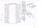
- One participant seeks to understand the circuit's purpose, suggesting it may be used to switch between star and delta connections.
- Another participant discusses the circuit's role in measuring phase voltage and proposes a calculation for the Y phase voltage at the microcontroller input.
- A third participant challenges the arithmetic of the proposed voltage calculation, indicating a potential error in the use of the k multiplier.
- There is a request for a more readable schematic to aid in understanding the circuit.
Areas of Agreement / Disagreement
Participants express uncertainty about the circuit's purpose and the accuracy of the voltage calculations. There is no consensus on the correct interpretation or application of the circuit.
Contextual Notes
The discussion lacks detailed information about the circuit schematic and the specific roles of the components involved, which may affect the understanding of the circuit's function.