Variable Gain Preamplifier using dc control voltage

  • Thread starter nauman
  • Start date
9 replies · 2K views · last reply
nauman
Messages
98
Reaction score
5
TL;DR
Orcad Capture simulatin of transistors based Variable Gain Preamplifier is not working properly
Hi all

I am trying to simulate input stage of a variable gain preamplifier for acoustic hydrophone operating in frequency range of 90KHz to 110KHz. It is transistor based preamplifier. The gain of preamplifier (Q01) is controlled through dc control voltage (Vc) connected with base of Q04 transistor through R05. I have attached the Orcad Capture Schematic snapshot.

The problem is that whatever dc control i set, output is still zero!

Any help in this regard is much appreciated.

Schematic of a transistor preamplifier input stage with an AC source V2 feeding diodes CR01 and CR02 and transistor Q01, a DC control voltage Vc of 4Vdc driving Q04 through R05, and a transformer-coupled load with L3, L4 and R6.
 
Is ##V_C## connected backwards? Also, what is the purpose of ##R_{03}##? I'm not understanding that part of the bias circuit...

EDIT/ADD -- Where did you get this circuit from?
 
OK, I haven't really solved this circuit. It basically looks ok. But here are my impressions based on a bunch of quick calculations with big approximations and maybe errors:
1) The DC bias looks ok at about 4mA.
2) The first stage gain of R02⋅Ie/Vt is about 260. So 260mV into the tank output filter. I would expect something like 4 to 8V at the output.
3) The LC tank output filter looks OK at 100KHz and Q=2. The load isn't significant compared to R02 or Zc, but see the next comment. I'm assuming the transformer steps the voltage up, not down.
4) Is your transformer backwards? I'm not sure about the ORCAD notation, but if the magnetizing inductance is 1.2mH seen from the left side and 4.2uH from the right, that's a turns ratio of 17:1, right?

Have you verified the simulator measurements of internal stuff with "rule of thumb" analysis? You say the signal is zero. Where is it zero? Which voltages and/or currents?

Maybe @Baluncore can set us straight. He's good at this and usually works harder than us.
 
nauman said:
The problem is that whatever dc control i set, output is still zero!
I think you have a modelling problem, not a circuit problem.
Simulation works in LTspice using 2x BC547.
Voltage gain is adjustable from 5 to 18, as Vc goes from -8.0 to -0.5 volt.

Transformer is matching Q1 collector load of 1k62 to 50R output.
Zratio = 1k62 / 50R = 32.4 down.

LTspice schematic of a variable gain amplifier with two BC547B transistors Q1 and Q4, a control voltage source Vc, a 1N4148 diode clamp pair, and a transformer K1 coupling to output R6 50R.
 
Attachments
Baluncore said:
I think you have a modelling problem, not a circuit problem.
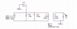
Thanks very much for help. I think you are right. I have problem in simulating the transformer in Orcad Capture as i am trying to simulate filter circuit connected with Q01 collector standalone and have following errors!
"ERROR -- Node N27120 is floating
ERROR -- Node N27066 is floating
ERROR -- Voltage source and/or inductor loop involving V_V1
You may break the loop by adding a series resistance"
Have you any experience with transfrmers simulations in Orcad Pspice?
 
Attachments
  • Schematic of a coupled-inductor circuit with a sinusoidal source V1 (VOFF = 0, VAMPL = 5, FREQ = 100k), capacitor C01 0.1u, R02 1.62k, C04 2150p, L3 1.2mH and L4 4.2uH linked by K1 (Kbreak, COUPLING = 0.99), with R6 50 ohm load.
    Filter_Circuit.jpg
    16.3 KB · Views: 71
Sorry, but no experience in the last 25 years with Orcad.

Spice simulators have a steep learning curve, which sometimes overhangs the climber.
I guess you have GND_0 floating because it is not grounded to ground node 0 of the simulation.
 
nauman said:
Have you any experience with transfrmers simulations in Orcad Pspice?
30 years ago I used PSpice a lot, LOL. Any knowledge there was lost long ago.
Like Baluncore, I'm an LTSpice convert. But really, I'm not a big fan of simulators for circuits that can be done by hand. Granted, you're stupid if you don't check with a simulator at some point. But they aren't great for design or understanding, you just get results.
 
Last edited:
Anyway, I think your next step is to either start deleting things, or build the circuit up bit by bit. Get rid of the transformer and see if that helps. The whole Q4 network can be replaced with a current source...
 
Also, recheck all of your trace junctions. I used to dislike ORCAD because traces don't (didn't) automatically connect. Maybe follow the old Mil-Spec rule that schematics should never have junctions where 4 (or more) traces connect. Then you only have crossings (not connected) and tees (connected). It makes it easy to check visually and (bonus! If you're a time traveler) is compatible with old crappy copiers and blueprint machines.
 
Baluncore said:
I guess you have GND_0 floating because it is not grounded to ground node 0 of the simulation.
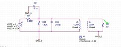
I am able to simulate by adding a small resistance in series with source V1 and grounding the source but still output is not correct i.e. 1mVpp across 50 ohm load whereas it should be around 800mVpp!
 
Attachments
  • Circuit schematic in a simulator showing a voltage source V1 (VOFF = 0, VAMPL = 5, FREQ = 100k) feeding R7 0.0001 and a coupling capacitor C01 0.1u, then R02 1.62k and C04 2150p to ground, a 1.2mH inductor L3 and a coupled inductor L4 38uH with K1 coupling 0.99 driving load R6 50 ohm.
    Filter_Circuit2.jpg
    17.2 KB · Views: 65