Water cooler radiator with unusual air flow direction

AI Thread Summary
The discussion focuses on finding a suitable radiator for a DIY air cooling project to regulate water temperatures up to 90°C. The user requires a radiator that allows air to flow through its side surface due to environmental constraints, rather than the typical top-down flow of automotive radiators. Suggestions include using automotive heat exchangers, oil coolers, or heater cores, and considering designs like zig-zagging tubes or finned tubes to enhance heat exchange efficiency. The importance of maintaining airflow direction and minimizing downstream cooling effects is also highlighted. Overall, the conversation emphasizes the need for creative solutions in radiator design to meet specific project requirements.
pozsar
Messages
1
Reaction score
0
TL;DR Summary
searching for pre manufactured radiator suitable for airflow from the 'side surface'
Hi everyone!

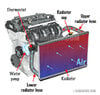
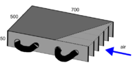
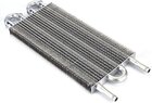
I'm doing a DIY project in which I have to use air cooling to regulate water temperatures of max 90°C. I want to use some cheap (possibly even used) pre-manufactured radiator to do the job for me (since I'm unable to make finned pipes with tight enough fittings to provide sufficient heat conduction between the tube and sheets), but I have environment constraints that make it impossible to channel the air through the largest surface like automotive radiators do (pic 1). I have to direct air through the 'side surface' (pic 2). I simply need long parallel aluminum sheets with tubes going through them. The dimensions of the radiator are planned to be roughly 50x500x700mm and the inner diameter of the tube should be ~10mm. I have been searching through the internet for days, but I'm not happy with my results. The best match at the moment is some oil cooler radiator which I find unnecessarily high in quality for my application (pic 3).
How can I find a radiator that is suitable for this? In what field do they use such radiators?
 

Attachments

  • 1.jpg
    1.jpg
    53.8 KB · Views: 75
  • 2.PNG
    2.PNG
    7.5 KB · Views: 97
  • 3.jpg
    3.jpg
    75.8 KB · Views: 76
Engineering news on Phys.org
You could use a 25 mm thick heat exchanger and mount it at an angle similar to the heat exchanger I built for heating my shop as shown in the photo below. The photo does not show the spreader vanes inside the transition piece between the blower and the heat exchanger plenum. Look for automotive heat exchangers - radiators, air conditioner condenser heat exchangers, oil coolers, or possibly heater cores.

Heat Exchanger.jpg
 
  • Like
Likes pozsar, dlgoff and berkeman
Welcome to PF.

Consider a bare 10 mm tube, without fins, folded back and forth across the airflow many times. Place the tube in a zig-zag-ing across the airflow, from the outlet of the air to the inlet, as a counterflow heat exchanger.

Now consider doing the same with finned tube, designed for use as a heat exchanger in an air compressor or a refrigerator. If the bend radius is too tight, use separate 180° elbows on either side.

It could be bent from a single tube, as a two layer structure, like a helix, flattened, skewed and staggered, to fit in the rectangular box.
 
  • Like
Likes pozsar and Tom.G
Welcome, @pozsar !

I hope that you are aware of the air cooling effect being quickly reduced downstream.
What is moving the air?
 
Posted June 2024 - 15 years after starting this class. I have learned a whole lot. To get to the short course on making your stock car, late model, hobby stock E-mod handle, look at the index below. Read all posts on Roll Center, Jacking effect and Why does car drive straight to the wall when I gas it? Also read You really have two race cars. This will cover 90% of problems you have. Simply put, the car pushes going in and is loose coming out. You do not have enuff downforce on the right...
I'm trying to decide what size and type of galvanized steel I need for 2 cantilever extensions. The cantilever is 5 ft. The space between the two cantilever arms is a 17 ft Gap the center 7 ft of the 17 ft Gap we'll need to Bear approximately 17,000 lb spread evenly from the front of the cantilever to the back of the cantilever over 5 ft. I will put support beams across these cantilever arms to support the load evenly
Thread 'What's the most likely cause for this carbon seal crack?'
We have a molded carbon graphite seal that is used in an inline axial piston, variable displacement hydraulic pump. One of our customers reported that, when using the “A” parts in the past, they only needed to replace them due to normal wear. However, after switching to our parts, the replacement cycle seems to be much shorter due to “broken” or “cracked” failures. This issue was identified after hydraulic fluid leakage was observed. According to their records, the same problem has occurred...
Back
Top