What's the difference in resistance between A and B vs A and C?

Click For Summary

Discussion Overview

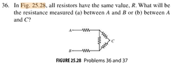
The discussion revolves around understanding the difference in resistance measurements between points A and B versus A and C in a circuit. Participants explore the calculations and circuit configurations necessary to determine these resistances, addressing both theoretical and practical aspects of circuit analysis.

Discussion Character

  • Technical explanation
  • Conceptual clarification
  • Debate/contested
  • Mathematical reasoning

Main Points Raised

  • Some participants express confusion about how to calculate the resistance between A and B compared to A and C, noting the need for different circuit diagrams for each case.
  • One participant suggests that the equivalent resistance between A and B can be calculated by merging resistors in series and calculating parallel resistances.
  • Another participant proposes that the resistor connected to B does not affect the resistance between A and C, as it is an open-ended connection.
  • Some participants attempt to derive the equivalent resistance using different configurations and calculations, leading to varying results and expressions for the resistances.
  • There are discussions about the concept of a 'short circuit' and its implications for the circuit analysis, with some participants seeking clarification on this term.
  • Several participants express uncertainty about their calculations and seek further explanations or corrections from others.

Areas of Agreement / Disagreement

There is no consensus on the calculations or the correct approach to determining the resistances between A and B and A and C. Multiple competing views and methods are presented, and participants continue to seek clarification and corrections.

Contextual Notes

Participants mention the need to alter circuit diagrams based on the specific resistance being calculated, indicating that assumptions about circuit configuration play a significant role in the analysis. There are also references to potential errors in calculations that remain unresolved.

MermaidWonders
Messages
112
Reaction score
0
View attachment 7919

I tried redrawing the above circuit so that it resembles more like the circuit diagrams we see from day to day. However, what confused me was when it asks for the resistance measured between A and B versus between A and C What's the difference between those two, and how would the calculations differ in each case?
 

Attachments

  • Screen Shot 2018-03-10 at 18.51.43.png
    Screen Shot 2018-03-10 at 18.51.43.png
    5.8 KB · Views: 122
Last edited:
Mathematics news on Phys.org
MermaidWonders said:
I tried redrawing the above circuit so that it resembles more like the circuit diagrams we see from day to day. However, what confused was when it asks for the resistance measured between A and B versus between A and C? What's the difference between those two, and how would the calculations differ in each case?

As for part (a), I tried to find the ${R}_{eq}$ of the entire circuit since I thought you must go through the whole circuit before arriving at B from A, but I don't think that that would get me the answer. :( Now, I'm even more confused... :(
 
Last edited:
2nd question:

View attachment 7920

I know this question's kinda lame, but it's just that when I tried to solve it, I couldn't get the right answer. (I got 3.375 $\times$ $10^{-9}$ A.) :(
(Answer = 1.5 mA)
 

Attachments

  • Screen Shot 2018-03-10 at 21.10.15.png
    Screen Shot 2018-03-10 at 21.10.15.png
    3.2 KB · Views: 116
MermaidWonders said:
https://www.physicsforums.com/attachments/7919

I tried redrawing the above circuit so that it resembles more like the circuit diagrams we see from day to day. However, what confused was when it asks for the resistance measured between A and B versus between A and C? What's the difference between those two, and how would the calculations differ in each case?

Hi MermaidWonders! ;)

To find the resistance between A and B, we can rearrange the circuit as:
\begin{tikzpicture}
%preamble \usepackage{circuitikz}
\draw
(0,0) node
{A} to [R, *-] (2,0) to (2,1) to [R, -*] (4,1) to [R] (6,1) to (6,0) to [R, -*] (8,0) node
{B}
(2,0) to (2,-1) to [R] (6,-1) to (6,0);
\end{tikzpicture}

Can you merge the resistors in series together?
And calculate the resitance of parallel resistors?

For the resistance between A and C we need:
\begin{tikzpicture}
%preamble \usepackage{circuitikz}
\draw
(0,0) node
{A} to [R, *-] (2,0) to (2,-1) to [R] (4,-1) to [R] (6,-1) to (6,0) to [short, -*] (7,0) node
{C}
(2,0) to (2,1) to [R] (6,1) to (6,0)
(4,-1) to [R, -*] (4, -3) node[below] {B} ;
\end{tikzpicture}
The resistor to B is a 'loose end' here, which does not participate.
Can you find the resistance between A and C?​
 
Thanks for your reply! As for this question, I got the same re-drawn circuit diagram as the one you have here for part (a), but I'm totally lost as to how you got part (b) in order to get the resistance for part (b). Can you please explain?
 
MermaidWonders said:
Thanks for your reply! As for this question, I got the same re-drawn circuit diagram as the one you have here for part (a), but I'm totally lost as to how you got part (b) in order to get the resistance for part (b). Can you please explain?

Just by deforming the circuit.
An intermediate step is:
\begin{tikzpicture}
%preamble \usepackage{circuitikz}
\draw
(0,0) node
{A} to [R, *-] (2,0) to [R] (4,-2) to [R, -*] (6,0) node
{C}
(2,0) to [R] (6,0)
(4,-2) to [R, -*] (2, -3) node[below] {B} ;
\end{tikzpicture}
And I've separated C a bit with a separate connection, which is equivalent, since it behaves like a 'short'.​
 
I like Serena said:
Hi MermaidWonders! ;)

To find the resistance between A and B, we can rearrange the circuit as:
\begin{tikzpicture}
%preamble \usepackage{circuitikz}
\draw
(0,0) node
{A} to [R, *-] (2,0) to (2,1) to [R, -*] (4,1) to [R] (6,1) to (6,0) to [R, -*] (8,0) node
{B}
(2,0) to (2,-1) to [R] (6,-1) to (6,0);
\end{tikzpicture}

Can you merge the resistors in series together?
And calculate the resitance of parallel resistors?

For the resistance between A and C we need:
\begin{tikzpicture}
%preamble \usepackage{circuitikz}
\draw
(0,0) node
{A} to [R, *-] (2,0) to (2,-1) to [R] (4,-1) to [R] (6,-1) to (6,0) to [short, -*] (7,0) node
{C}
(2,0) to (2,1) to [R] (6,1) to (6,0)
(4,-1) to [R, -*] (4, -3) node[below] {B} ;
\end{tikzpicture}
The resistor to B is a 'loose end' here, which does not participate.
Can you find the resistance between A and C?​


Is the resistance between A and B equal to $\frac{7}{2R}$?​
 
MermaidWonders said:
Is the resistance between A and B equal to $\frac{7}{2R}$?

Not according to my calculations.
How did you get that?
 
I like Serena said:
Not according to my calculations.
How did you get that?

Oops, I just realized that I messed up... Let's try again.

Top 2 resistors of parallel portion of the circuit are in series with each other $\implies$ $R = R + R = 2R$

Bottom resistor of parallel portion of the circuit in parallel with top 2 resistors $\implies$ $\frac{1}{{R}_{eq}}$ = $\frac{1}{2R}$ + $\frac{1}{R}$ = $\frac{3}{2R}$ $\implies$ $\therefore$, ${R}_{eq}$ = $\frac{2R}{3}$

Now, this ${R}_{eq}$ will be in series with the remaining resistors $\implies$ ${R}_{total}$ = $\frac{8R}{3}$?

- - - Updated - - -

I like Serena said:
Just by deforming the circuit.
An intermediate step is:
\begin{tikzpicture}
%preamble \usepackage{circuitikz}
\draw
(0,0) node
{A} to [R, *-] (2,0) to [R] (4,-2) to [R, -*] (6,0) node
{C}
(2,0) to [R] (6,0)
(4,-2) to [R, -*] (2, -3) node[below] {B} ;
\end{tikzpicture}
And I've separated C a bit with a separate connection, which is equivalent, since it behaves like a 'short'.​


Oh, I see. Now, with this new diagram, how would one go about solving for the resistance between A and C?

P.S.: What's a 'short'? Do you mean the extra connection to C? If so, how come the 'short' won't affect C?​
 
  • #10
MermaidWonders said:
Oops, I just realized that I messed up... Let's try again.

Top 2 resistors of parallel portion of the circuit are in series with each other $\implies$ $R = R + R = 2R$

Bottom resistor of parallel portion of the circuit in parallel with top 2 resistors $\implies$ $\frac{1}{{R}_{eq}}$ = $\frac{1}{2R}$ + $\frac{1}{R}$ = $\frac{3}{2R}$ $\implies$ $\therefore$, ${R}_{eq}$ = $\frac{2R}{3}$

Now, this ${R}_{eq}$ will be in series with the remaining resistors $\implies$ ${R}_{total}$ = $\frac{8R}{3}$?

Yep. That's correct. (Nod)

MermaidWonders said:
Oh, I see. Now, with this new diagram, how would one go about solving for the resistance between A and C?

P.S.: What's a 'short'? Do you mean the extra connection to C? If so, how come the 'short' won't affect C?

Just leave out the resistor to B and do the same thing:
\begin{tikzpicture}
%preamble \usepackage{circuitikz}
\draw
(0,0) node
{A} to [R, *-] (2,0) to (2,-1) to [R, -o] (4,-1) to [R] (6,-1) to (6,0) to [short, -*] (7,0) node
{C}
(2,0) to (2,1) to [R] (6,1) to (6,0);
\end{tikzpicture}
A 'short' means 'short circuit', which is a connection between 2 points with no (or negligible) resistance.
If that's an unintended connection, we'll get a bad result.
But in this case it's only to clarify the circuit, without actually making a connection to any other point in the diagram.
As such it has no impact whatsoever on the result.​
 
  • #11
What happened to B now? Why is it gone?
 
  • #12
MermaidWonders said:
What happened to B now? Why is it gone?

Since B is an open ended connection, no current can flow through B.
Therefore the resistor to B can be left out without changing the resistance between A and C.
And now we can calculate that resistance...
 
  • #13
I like Serena said:
Since B is an open ended connection, no current can flow through B.
Therefore the resistor to B can be left out without changing the resistance between A and C.
And now we can calculate that resistance...

OK... So, to sum up, you would need 2 different circuit diagrams to refer to depending on whether you need the resistance between A and B or A and C, right, and for each case, you must alter the diagram such that you'll end up being able to calculate the equivalent resistance as you would for any circuit?
 
  • #14
MermaidWonders said:
OK... So, to sum up, you would need 2 different circuit diagrams to refer to depending on whether you need the resistance between A and B or A and C, right, and for each case, you must alter the diagram such that you'll end up being able to calculate the equivalent resistance as you would for any circuit?

Yep. (Nod)
 
  • #15
OK, thanks! :)
 
  • #16
Oh, and about the second part... (Wait)

We know now that the resistance between A and B is $R_{AB}=\frac 83R$ with $R=1\text{ k}\Omega$ and $V=6\text{ V}$.
So the total current is:
$$I_{total}=\frac V{R_{AB}}=\frac {6\text{ V}}{\frac 83\cdot 1\text{ k}\Omega} = 2.25 \text{ mA}$$
Since the current is split between 1R along the vertical branch and 2R along the branch through C, it follows that $\frac 23$ of the current must flow through the vertical branch, which is:
$$I_{vertical} = \frac 23 \times 2.25 = 1.5\text{ mA}$$
 
  • #17
I now understand where I went wrong in question #37. I didn't use $\frac{8R}{3}$ as the equivalent resistance since I messed up in the beginning... I finally got the right answer, although I do agree that your reasoning about the currents is much faster :) Many thanks again!
 

Similar threads

  • · Replies 10 ·
Replies
10
Views
2K
  • · Replies 14 ·
Replies
14
Views
1K
  • · Replies 4 ·
Replies
4
Views
1K
  • · Replies 21 ·
Replies
21
Views
2K
Replies
8
Views
4K
  • · Replies 14 ·
Replies
14
Views
4K
  • · Replies 16 ·
Replies
16
Views
4K
  • · Replies 21 ·
Replies
21
Views
4K
  • · Replies 38 ·
2
Replies
38
Views
3K
  • · Replies 1 ·
Replies
1
Views
2K