Where is the lost energy in this example?
Click For Summary
Discussion Overview
The discussion revolves around the phenomenon of energy loss when connecting charged and uncharged capacitors. Participants explore the implications of this energy loss in the context of circuit theory, electromagnetic radiation, and charge redistribution, addressing both theoretical and practical aspects of the scenario.
Discussion Character
- Exploratory
- Technical explanation
- Conceptual clarification
- Debate/contested
- Mathematical reasoning
Main Points Raised
- One participant notes that connecting a charged capacitor to an uncharged one results in a final energy that is less than the initial energy, prompting the question of where the lost energy goes.
- Another participant suggests that energy loss occurs due to electrons jumping across the gap in the connecting wires, which radiates electromagnetic waves and thus loses electrical potential energy.
- Some participants argue that using a lumped element circuit model may not accurately represent real-world situations, proposing the need for a more complex model that includes inductance to account for energy oscillations and losses.
- It is mentioned that current flowing in the circuit leads to radiation, which carries away energy, and that the distribution of charge affects potential energy due to changes in repelling forces between charges.
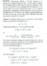
- One participant provides a mathematical analysis of the energy loss in the context of an RLC circuit, emphasizing that energy conservation requires considering the entire system, including resistive losses.
- Several references to academic papers are made, suggesting further reading on the topic, although some participants express reluctance to access paid resources.
- A participant highlights the importance of charge redistribution when capacitors are connected, proposing that the physics of energy loss is intrinsically related to the charge configuration and potential energy distribution.
Areas of Agreement / Disagreement
Participants express multiple competing views regarding the mechanisms of energy loss and the adequacy of circuit models. There is no consensus on a single explanation, and the discussion remains unresolved with various hypotheses presented.
Contextual Notes
Some discussions involve assumptions about ideal conditions, such as zero resistance in wires, and the implications of including real-world factors like resistance and radiation are noted but not fully resolved.

Similar threads
- · Replies 5 ·
- · Replies 1 ·
- · Replies 1 ·
- · Replies 152 ·
- · Replies 11 ·
- · Replies 9 ·
- · Replies 20 ·
- · Replies 4 ·
- · Replies 22 ·
- · Replies 9 ·