Why do charges redistribute when capacitors are reconnected?

  • Level: Undergrad 
  • Thread starter Thread starter Calpalned
  • Start date Start date
  • Tags Tags
    Capacitors
Join the discussion
Registration is free. Start your own thread to ask a follow-up.
5 replies · 2K views · last reply
Calpalned
Messages
297
Reaction score
6
In an example from my textbook, two capacitors are fully charged and then disconnected from the battery. (The full text is on the bottom of the thread).
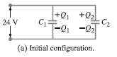
Circuit schematic of two capacitors in an initial configuration: a 24 V battery on the left, C1 in the middle with +Q1 on top and -Q1 below, and C2 on the right with +Q2 on top and -Q2 below, labeled (a) Initial configuration.

Initially, the positive charge is on top, negative on the bottom.
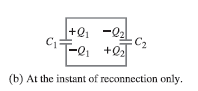
Circuit diagram of two capacitors C1 and C2 joined by wires, with charges +Q1 and -Q2 on top plates and -Q1 and +Q2 on bottom plates, labelled (b) At the instant of reconnection only.

How did this occur? This is the part that I don't understand. Originally the top had two positive charges and now it has both positive and negative. Is this natural, or was something done during the re-connection?
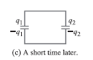
Circuit diagram of two capacitors connected in parallel, labeled (C) A short time later, with charges q1 and q2 on the top plates and -q1 and -q2 on the bottom plates.

So the charges move back to the same configuration as in (A) - positive on top, negative on the bottom. This makes sense. Once again, I don't understand part B, because part B doesn't seem to fit the sequence. A can go to C, but B doesn't fit.

Below is the full example, if it helps
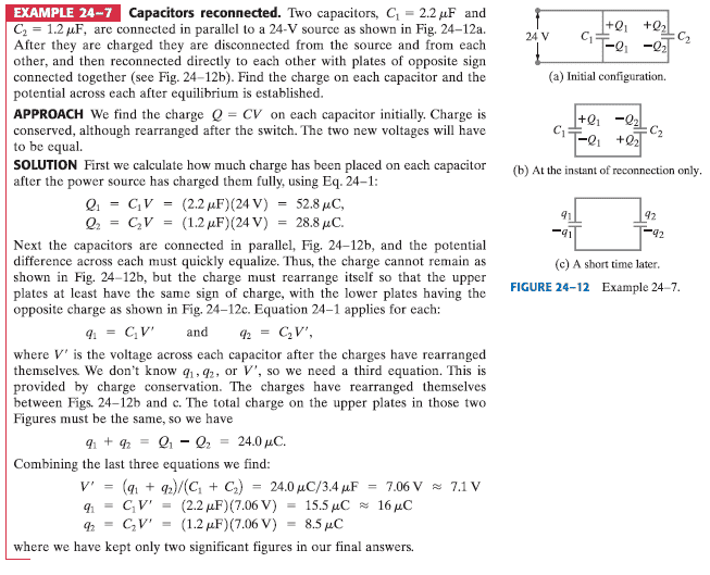
Three-panel circuit diagram of two capacitors C1 = 2.2 μF and C2 = 1.2 μF in parallel with a 24 V source: (a) initial configuration with charges +Q1, -Q1, +Q2, -Q2; (b) at reconnection; (c) a short time later with charges q1 and q2.

Thank you.
 
  • Like
Likes   Reactions: kbr2020
Physics news on Phys.org
Looks like C2 is simply "turned around" between the two first diagrams, i.e. the connectors between C1 and C2 are swapped in the second diagram compared to the first.
 
  • Like
Likes   Reactions: davenn
Calpalned said:
How did this occur? This is the part that I don't understand. Originally the top had two positive charges and now it has both positive and negative. Is this natural, or was something done during the re-connection?
Read the second sentence of the first paragraph of the question. Carefully.
 
  • Like
Likes   Reactions: davenn
Filip Larsen said:
Looks like C2 is simply "turned around" between the two first diagrams, i.e. the connectors between C1 and C2 are swapped in the second diagram compared to the first.

Yes

DaleSpam said:
Read the second sentence of the first paragraph of the question. Carefully.

and yes :smile:
 
CrazyNinja said:
But even otherwise, if the battery was disconnected and the capacitors weren't the charge distribution would still be as shown in (b). It has to be to satisfy kirchhoffs loop rule. No reconnection is required, charge will flow automatically.

You may want to re-think that. The removal of the battery leaves the system in the state shown at (a). It is already in equilibrium and no charge will flow.
 
jbriggs444 said:
You may want to re-think that. The removal of the battery leaves the system in the state shown at (a). It is already in equilibrium and no charge will flow.

Yeah it is. Sorry for that. I'll jus delete the previous post. Thanks!