gneill said:
When you flip the inputs you no longer have a negative feedback situation (where a portion of the output is fed back to the negative input of the op amp). The mechanism that forces ##v^+## equal to ##v^-## is no longer present. So indeed, the internal circuitry of the op amp is going to produce something different.
Think of the op amp as a dependent voltage source with some amplification factor A so that ##V_o = A(v^+ - v^-)## and reanalyze the circuit.
I know this question and your reply was a while back now but hopefully you're still around. I finally came around to analyzing the circuit with the input resistor, dependent voltage source, and output resistance of the op amp, and I found that it still acts the same way pretty much, with a tiny detail of difference. So here's what I did:
1) Regular Inverting Op Amp Circuit:
2) Now flip the Op Amp inputs:
You see from both final equations (bottom of each picture), they are almost exactly the same except the "AR2" term in the first case is negative and in the second case positive.
How does this affect things? If I put this up on Desmos, and set some values for R1, R2, Ri, Ro, and A, I get the following:
They are pretty much the same line. And if I tried to see more exact values, I find that there is indeed a very small difference, but it's essentially insignificant:
So it seems like even in the more detailed model, flipping the op amp's inputs does not change the output much at all. I suppose perhaps I'd have to go down to the CMOS level next to analyze once more. What do you all think?
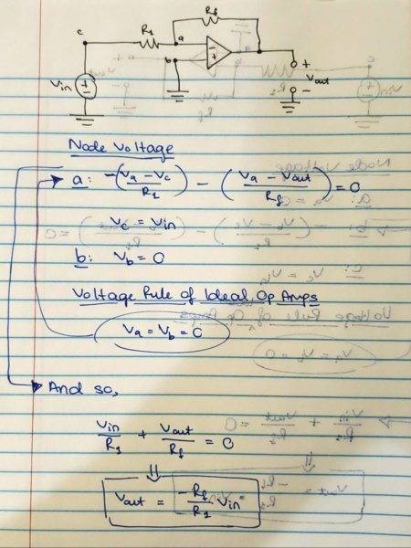 However, when I switch the terminals of the op amp and follow through with the equations, I get the same Vout.
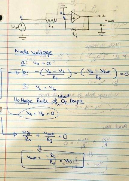 So my question then is what is the difference? I know there is other circuitry involved with the op amp internally, so I guess that's involved but I haven't gotten there yet.


