Why doesn't my analog delay line show reflections in Multisim?

6 replies · 4K views · last reply
Hiranya Pasan
Messages
30
Reaction score
3
I'm trying to construct an analog delay (series of low pass filters) and demonstrate the properties of a transmission line (reflection, attenuating etc.) using a multisim simulation (my attempt attached below). But on the oscilloscope I don't get any kind of reflection. What should I do?
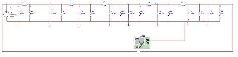
Multisim schematic of a ladder of eight LC low-pass sections: series inductors L1 to L8 at 2.0mH each, shunt capacitors C1 to C8 at 180nF each, and shunt resistors R1 to R8 at 100 ohms, driven by a 1 V 10000 Hz source V1, with an oscilloscope XSC1 connected at the output end.

Thank you
 
Can you show us the waveforms you are getting? Also, I don't think C1 will do much of anything useful if you are driving the input to the TL with an idea voltage source. What is the output resistance that you have assigned to V1? Is V1 a sine wave source or a pulse source?
 
This is the wave form I get for sine and square pulse inputs
Oscilloscope screenshot from Multisim showing two red periodic waveforms on a black grid: an upper sinusoid-like trace and a lower trace with a similar frequency, offset vertically, both repeating across the display.
Oscilloscope screenshot in Multisim: a red sinusoid with about ten cycles on top, and a red square wave with a similar number of cycles below, both on a black grid.

I get the the delay output but no reflection effects. First I tried to get the waveform for an open circuit.
 
What is the target Zo for your TL? It sure looks very lossy -- are those 1000 Ohm resistors in the TL?
 
berkeman said:
What is the target Zo for your TL? It sure looks very lossy -- are those 1000 Ohm resistors in the TL?

No such target, but I only need to demonstrate delay and reflection effects. No need to use specific values.
 
Hiranya Pasan said:
No such target, but I only need to demonstrate delay and reflection effects. No need to use specific values.
Well, you need the Zo to calculate the expected reflections of any mismatched termination, no?

Also, why is it so lossy? The parallel resistances are meant to represent the conductance of the dielectric insulator in the TL (at the test frequency). 1000 Ohms is way too much conductance, IMO.
 
I don't think the circuit as drawn will work because it's not a transmission line. The main issue is each filter bank is referenced to the same potential. To make this work you'll need inductance in the return between each too. Also, to make the lumped model approximation correct the time constant of each stage has to be >> than the edge rate of the signal (which is not the same as it's frequency). (Note: because "ground" is not the same on both sides of the filter you'll need to find the delay through the two port network. This is not the same as the equations you typically use for a garden variety LC filter.) This is definitely the hard way to do it but if you can make it work, and know why it is working, then you'll definitely have a much better understanding of transmission lines.
 
  • Like
Likes   Reactions: berkeman