Discussion Overview
The discussion revolves around issues encountered while simulating common mode current in LTSpice. Participants explore the discrepancies between their simulation results and expected outcomes, focusing on circuit configurations, component values, and the behavior of the circuit under different conditions. The conversation includes technical details about pulse signals, resistances, and filtering effects.
Discussion Character
- Technical explanation
- Debate/contested
- Mathematical reasoning
- Experimental/applied
Main Points Raised
- One participant notes a discrepancy in simulation results compared to another software, particularly regarding the transformation of square signals into pulses through a capacitor.
- Another participant suggests that missing inductors in the LTSpice schematic may affect the simulation and requests the circuit file for further analysis.
- Concerns are raised about the simulation speed and the need for adjustments in the pulse generator settings, including resistance values and transient analysis time.
- There is a discussion about the internal resistance of the pulse generator and its impact on current measurements, with suggestions to simplify the circuit by removing unnecessary resistances.
- A participant describes issues with oscillations when adding a common mode filter, attributing them to the circuit's configuration and grounding problems.
- Another participant explains the importance of having a DC voltage reference path to ground and discusses the effects of capacitors in the circuit, including their role in resonance and signal behavior.
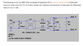
- One participant proposes a different simulation setup for testing common mode and differential signals, detailing parameters and analysis methods to evaluate circuit performance.
- Questions arise regarding the utility of previously used capacitors in the circuit and the absence of expected oscillations in the filtered signal, prompting further exploration of circuit dynamics.
Areas of Agreement / Disagreement
Participants express various viewpoints and suggestions, but no consensus is reached on the optimal circuit configuration or the reasons behind the observed behaviors. Multiple competing views remain regarding the effects of specific components and circuit setups.
Contextual Notes
Participants mention limitations related to circuit complexity, internal resistances, and the influence of various components on the simulation results. There are unresolved questions about the specific roles of certain resistors and capacitors in the circuit's behavior.
Who May Find This Useful
Individuals interested in circuit simulation, particularly in the context of common mode current and filtering techniques, may find the discussion relevant. This includes students, engineers, and hobbyists working with LTSpice or similar simulation software.