Backyard Tow Rope Troubleshooting: Motor Binding Issues

In summary, the problem is that the "middle" wrap needs to continuously slide sideways while under tension. It cannot slide sideways because it is under tension, so the incoming rope goes over the top of the "middle" wrap, travels around, and comes out pinched underneath exactly as shown in the lower photo.
  • #1
rlay023
13
3
TL;DR Summary
Rope wrapped around pulley binds under itself.
Hello -

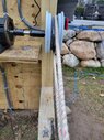
We are building a backyard tow rope for my course. All of the electrical components are working as designed; however, the pulley can't consitently grip the rope when only placed around the rim. When looped around 1.5 times the rope continually shifts underneath itself causing the motor and drive shaft to bind.

Any thoughts on what is causing this issue or other components that could be added to the system to improve performance?
 
Engineering news on Phys.org
  • #2
Can you attach a picture of the setup? Use the "Attach files" link below the Edit window to upload a JPEG or PDF file with the image. Thanks
 
  • #3
Both ends of the rope need to be kept in tension at all times. Also, fairleads can help to prevent the rope getting so far out of position.

In this picture you can see a white fairlead pulley on the left. That leads the rope into the winch at the correct angle, regardless of tension.

You can also see the final wrap of rope at the top of the winch goes over a finger, then through a pinching device at the top. The purpose of all that is to maintain tension on the loose end.

1673538749004.png


On occasions where that goes wrong and the rope feeds under itself, it can be very difficult to make right again.
 
  • Like
  • Informative
Likes hutchphd, russ_watters and berkeman
  • #4
anorlunda said:
Both ends of the rope need to be kept in tension at all times. Also, fairleads can help to prevent the rope getting so far out of position.

In this picture you can see a white fairlead pulley on the left. That leads the rope into the winch at the correct angle, regardless of tension.

You can also see the final wrap of rope at the top of the winch goes over a finger, then through a pinching device at the top. The purpose of all that is to maintain tension on the loose end.

View attachment 320222

On occasions where that goes wrong and the rope feeds under itself, it can be very difficult to make right again.
I have the bottom idler tensioned with a ratchet strap. Are you thinking that isn't tight enough? I will take some pictures this evening and post.
 
  • Like
Likes berkeman
  • #5
I forgot, there's another possibility. Note the guide on this casting reel. It is a fairlead that moves left/right as you reel in to prevent the line from crossing itself.

1673548370136.png


In the video the drum of the spinning reel moves up and down as you reel in to prevent the line from crossing itself.

So I think we need more details on your setup and your problems before we can give an accurate answer.

Edit: Might your problem resemble this?
1673549382585.png
 
Last edited:
  • #6
The birds nest in the fishing reel isn't the problem as it is only looped around the drum once; however the rope always finds away to cross over itself within a few revolutions. I didnt have the entire rope under tension at the moment but here are a few pics that may help illustrate:
20230112_163326.jpg
20230112_163423.jpg
 

Attachments

  • 20230112_163339.jpg
    20230112_163339.jpg
    61 KB · Views: 66
  • #8
The fundamental problem is that the "middle" wrap needs to continuously slide sideways while under tension. It cannot slide sideways because it is under tension, so the incoming rope goes over the top of the "middle" wrap, travels around, and comes out pinched underneath exactly as shown in the lower photo. You can see this by wrapping a piece of rope around a round object, then turning the round object.

The equation that summarizes the problem is ##T_1/T_2 = e^{\mu\theta}##, where
##T_1## = rope tension on the tight side
##T_2## = rope tension on the slack side
##e## = Euler's number = 2.71828
##\mu## = the coefficient of friction between rope and pulley
##\theta## = the angle of wrap in radians

A pulley driving a belt or rope only works when there exists tension on the slack side, "back tension". That is because the drive pulley has a limiting ratio of tight side to slack side tension, as shown in the equation above.

When one wrap of 180 degrees does not provide enough "grab" to pull the rope properly, you have some options:
1: Tighten the rope. The tension ratio stays the same, but the difference between the tight side and slack side tension increases.
2: Drive the rope with a V-belt pulley. The rope wedges between the sides of the pulley, which increases the tension ratio by about five times for the same angle of wrap. The wedging action is the principle of V-belts. Make sure that the rope does not bottom in the pulley - it must be supported by the sides in order to get proper wedging action.
3: Increase the coefficient of friction by gluing rubber to the pulley.
4: Increase the angle of wrap using an idler pulley as in the sketch below. The idler pulley should have the largest practical diameter, ideally the same diameter as the drive pulley. The idler pulley should be on the slack side.
Pulley wrap.jpg

I got a good education in all of this when I designed a web drive that stopped pulling when at the high end of the speed range. It turned out that centrifugal force counteracted the slack side tension at high speed. The ratio of ##T_1/T_2## stayed the same, but when slack side tension got too low, so did the tight side tension.
 
  • Informative
  • Like
Likes Lnewqban and berkeman
  • #9
Thank you very much. The rotation is opposite with the bottom rope being wrapped and the top rope exiting the drive. Does that change the location of the pulley?

Also, could I mount a smaller idler pulley on a pole as show that would feed the bottom rope around the pulley at a higher point.
 
  • #10
A traditional capstan has a smoothly waisted drum to keep the turns central. The drum shown has a groove in the middle which will trap the turns.
 
  • Like
Likes Dullard
  • #11
If none of jrmilcher's suggestions work (note that none involve 'wrapping' the line completely around the pulley), you need a capstan (multiple turns). This is a common solution in the tube-drawing industry - it requires positive control (a guide) of the 'infeed' and 'outfeed' positions and some mechanism to maintain tension on the outfeed, but is fundamentally pretty simple. With proper guides, the capstan can be a simple cylinder.
 
  • #12
I have a very, very similar setup to rlay023's. I use almost exactly the same rim to drive my rope. And I also have experienced the very same problem: to get enough friction to drive the rope, you need to do two wraps; but a skier abruptly weighting the rope will cause slack that propagates and causes the knotting (sort of like a Munter Hitch) that rlay023 describes. I do agree that the channel in the center of the rim may contribute to knotting....

It looks to me as if rlay023 may already have tried increasing friction by putting tape around the center of the rim. I have tried that, but rope/rubber sheeting quickly degrades and isn't a solution.

I've also thought about adding one or two idler pulleys, but it seems to me that the most one can accomplish with idler pulleys is basically ensuring a little less than 360 degrees of contact with the drive wheel. I'm not sure if that's enough friction to prevent the rope from slipping. Is there a calculation I can do to figure out how much friction I'll produce/will need to propel 2+ skiers uphill?

I've had two other thoughts. One (reflected in the black-and-white sketch) is to add a series of pulleys on the uphill/skier (non-returning) side of the rope through which the rope is threaded. My theory is that those pulleys would prevent the slack from propagating back to the drive wheel and would stop knotting. I've attached a rough drawing to try and show what I'm describing (and I'm assuming that the slack is coming from the skier side of the rope, which I'm pretty sure is the case).

My second idea (reflected in my v. rough sketch that uses multiple colors to try and clarify what I'm talking about) is to add one or more freewheels in front of the drive-wheel and run one or more loops around them. They'd serve the same purpose as idler wheels, but my thinking is that by running two wraps around the freewheels, you could basically have three (partial) wraps around the drive-wheel, which would give you more friction. One alternative in that case would be to have multiple drive wheels in parallel, so that each new wrap goes around a different drive-wheel, thus eliminating the risk of knotting.

I'd welcome people's thoughts.

Addendum: I think some of my probs would be solved by using a bigger drive wheel, which I think would provide more friction, but my current gearing was designed to work with the gearing I have and if I go to a bigger wheel w/o changing gearing, I'm worried that I'll dislocate skiers' shoulders...But one question I have is: if I doubled the circumference of the drive wheel, would I roughly speaking double the amount of friction/traction produced on the rope (all other factors remaining unchanged)?
Screenshot 2024-02-12 at 5.06.54 PM.png
Screenshot 2024-02-12 at 5.07.08 PM.png
 
Last edited by a moderator:
  • #13
FCStorm said:
My theory is that those pulleys would prevent the slack from propagating back to the drive wheel
No pulley arrangement will prevent slack from propagating back to the drive wheel. You could, however, put a spring loaded pulley on the slack side that would take up the slack to maintain constant tension on the slack side.
FCStorm said:
if I doubled the circumference of the drive wheel
No change in maximum pulling force. The maximum pulling force is a function of slack side tension, angle of wrap, and friction coefficient as discussed in Post #8.

If you can make the arrangement in your second sketch work, the total angle of wrap on the drive pulley will be 500 to 600 degrees, or 9 to 10 radians. You might run into trouble with the belt interfering with itself.

Plugging that angle of wrap into the belt tension equation: ##T_1/T_2 = e^{\mu\theta}##, where
##T_1## = rope tension on the tight side
##T_2## = rope tension on the slack side
##e## = Euler's number = 2.71828
##\mu## = the coefficient of friction between rope and pulley, about 0.25 for synthetic rope on steel
##\theta## = the angle of wrap in radians, say 9.5

then ##\mu * \theta = 0.25 * 9.5 = 2.37##

and ##T_1/T_2 = e^{\mu\theta} = e^{2.37} = 10.7##

The rope will slip when the slack side tension is less than the tight side tension divided by 10.7. If the uphill skiers are pulling with a total force of 1000 lbs, then the slack side will need a minimum of 1000/10.7 = 95 lbs tension.

If you use an idler as shown in Post #8, the angle of wrap will be about 250 degrees, and the maximum ratio of tight side to slack side tension will be about 3:1. The minimum slack side tension for 1000 lbs on the tight side will be 1000 / 3 = 330 lbs.

FCStorm said:
multiple drive wheels in parallel
Yes. What counts is the total angle of wrap. If you weld two car wheels together, then put an idler at an angle to steer the rope from the first wheel to the second wheel, it will run without belts tangling or rubbing. Just make sure that both drive wheels are identical. The idler can be any size.

This system will work better if the drive is at the top of the hill. The length of rope on the tight side is shorter, so the change in length under load will be less. If the change in length under load is less, the loss of tension on the slack side is less.
 
  • #14
the slack pulley setup is sometimes called a 'dancer'
-it can be setup on air or a spring
...if there's a lot of slack maybe you need another wheel, not a rod,
similarly tensioned by a spring or air
--but it can be done by a rod, if the tolerance is not too large
 

Similar threads

  • Mechanical Engineering
Replies
2
Views
1K
Replies
4
Views
5K
  • Mechanical Engineering
Replies
4
Views
2K
Replies
4
Views
12K
  • Engineering and Comp Sci Homework Help
Replies
18
Views
1K
  • Mechanical Engineering
Replies
7
Views
2K
  • General Engineering
Replies
14
Views
6K
  • Electrical Engineering
Replies
5
Views
1K
Replies
3
Views
4K
Replies
2
Views
2K
Back
Top