- #1
SCHROEDERFPM
- 20
- 1
- TL;DR Summary
- Hi.
So I'm beginning to teach myself the basics and I'm working on a motorised lamp made from two camera lenses taken apart and assembled together.
I'm looking for help with wiring the motor and led together, and how to best set up my circuit.
(Mind you, I have literally just begun and have basically no clue what I'm doing but I'm making strides, so please as much detail as you would like to share would be helpful)
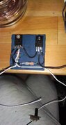
So far this is what I have:
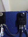
I have the power source, two triple in a battery case, negative to the T emitter, T output to the (-) of motor, T base through a resistor to the switch, switch to the (+) of motor.
I tried wiring the Led to this junction and the switch, but either the motor or the switch works not both simultaneously.
I tried wiring them parallel but I'm having some of the same issues, that or the led just stays on all the time or needs a seperate switch so I'm doing something wrong.
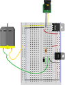
The second thing I'm working on is another lamp thing but with a fan inside, and this uses a 15v 3a wall input. For this one I tried to follow a blueprint for a system using two transistors to manage higher voltage as I'm just using a small cal and maybe one led in this.
This is a bit more out of my experience but I'll post a photo and any advice would be helpful.
(This is not connected yet just trying to figure out how to wire it.)
I have the power source, two triple in a battery case, negative to the T emitter, T output to the (-) of motor, T base through a resistor to the switch, switch to the (+) of motor.
I tried wiring the Led to this junction and the switch, but either the motor or the switch works not both simultaneously.
I tried wiring them parallel but I'm having some of the same issues, that or the led just stays on all the time or needs a seperate switch so I'm doing something wrong.
The second thing I'm working on is another lamp thing but with a fan inside, and this uses a 15v 3a wall input. For this one I tried to follow a blueprint for a system using two transistors to manage higher voltage as I'm just using a small cal and maybe one led in this.
This is a bit more out of my experience but I'll post a photo and any advice would be helpful.
(This is not connected yet just trying to figure out how to wire it.)