- #1
KTBMedia
- 6
- 9
- Homework Statement
- "It is desired to design a cup anemometer for wind speed, with a more sophisticated approach than the “average-torque” method commonly used in other problems. The anemometer's angular speed, ω, is a function of the anemometer's rotation angle, and is constantly changing (even for a constant wind speed). The design should achieve an approximately linear relation between wind velocity and rotation rate in the range 20 < U < 40 mi/h, and the anemometer should rotate at about 360 rpm at U = 30 mi/h. All specifications—cup diameter D, rod length L, rod diameter d, the bearing type, and all materials—are to be selected through your analysis. Make suitable assumptions about the instantaneous drag of the cups and rods at any given angle θ(t) of the system. Compute the instantaneous torque T(t), and find and integrate the instantaneous angular acceleration of the device. Develop a complete theory for rotation rate versus wind speed in the range 0 < U < 50 mi/h. Include actual commercial bearing friction properties."
- Relevant Equations
- For a hemispherical cup shape, the drag coefficient c_d = 1.4 for flow traveling toward the cup's opening, and c_d = 0.4 for flow traveling towards the closed, rounded side of the cup.
A fluid drag force, F_d, is given by F_d = 1/2*c_d*rho*A*v^2, where v is the speed of the body relative to the fluid, A is the effective cross-sectional area, and rho is the fluid density.
First, this class uses Frank White's Fluid Mechanics textbook. This particular problem is taken straight from chapter 7, which is on "Flow Past Immersed Bodies" and is basically focused on external flow, geometry effects, and boundary-layer conditions. So I imagine that the problem makes use of those concepts. Concepts covered in the book prior to this chapter include internal flow through ducts, the Moody chart, the Navier-Stokes equation, the Reynolds transport theorem, the Bernoulli equation, dimensional analysis / the Pi theorem, and basic shear stress / viscosity. All of those topics are fair game.
Second, because this problem has a lot of elements to it and things going on (asking us to decide on materials and everything), it's somewhat open-ended as a result. My professor has said that it's up to us to choose how many cups we'd like to have the anemometer to have. For simplicity, I think we'll go with a design that includes two cups.
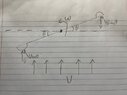
The professor recommended that our first step be to find a formula that estimates the instantaneous drag on the cups as a function of the rotation angle, θ. The first thing I did was draw a diagram of the setup. I'm assuming that the fluid velocity relative to the wind is what's most important, as that's what's causing the "drag" on each of the anemometer's cups. I also set up my equation for the drag force in such a way that only the component of the wind speed normal to the "face" of the cups are considered. I'm assuming that this is valid, though if there's a problem with that approach then please point it out to me!
Anyways, my initial force equations look like this. Note that "1" subscripts refer to the cup which has its opening facing the incoming wind (and is therefore rotating "with" the wind), and "2" subscripts refer to the cup with is faced in the opposite direction, and is therefore "fighting" the wind at any given angle.
$$
\begin{align*}
F_d1 & = \frac{1}{2} \rho A c_{d1} (v_{rel1})^2 \\
F_d2 & = \frac{1}{2} \rho A c_{d2} (v_{rel2})^2
\end{align*}
$$
Note that this doesn't account for the drag acting on the rotating rod between the two cups. Expanding it out a bit, accounting for the "relative" wind speeds as I mentioned earlier:
$$
\begin{align*}
F_d1 & = \frac{1}{2} \rho A c_{d1} (U \cos(\theta) - R \omega)^2 \\
F_d2 & = \frac{1}{2} \rho A c_{d2} (U \cos(\theta) + R \omega)^2
\end{align*}
$$
The values for cd are provided by the textbook. I've listed them in the "Relevant Equations" section.
I don't feel terrible about this approach, but I do admit that my logic might be kind of shaky. Due to the fact that the anemometer is rotating, technically a "1" cup will become a "2" cup and vice-versa after each 180-degree rotation of the device. I'm not sure if this hurts the validity of my equations.
The bigger problem I have with what I've done, is the fact that I don't think I've fully solved the "first" step of the problem. Sure, it's a formula for drag force with respect to theta, but it also includes omega - a non-constant. Not sure what to do about that.
I also tried to make a formula for the net torque of the system:
$$
\begin{align*}
M &= L (F_{d1} - F_{d2}) \\
&= \frac{1}{2} \rho R A ( 1.4(U \cos(\theta) - R \omega)^2 - 0.4(U \cos(\theta) + R\omega)^2 )
\end{align*}
$$
And that's about where I'm at right now. I feel like I probably want to find a formula for the angular velocity as a function of theta, but I've been playing around with it for a bit and I'm really not sure how to do that, and I kind of feel like I've hit a dead end right now. A classmate who's working on the same problem has said that he's going to try finding a function of the drag coefficient with respect to theta, as opposed to what I've done. Might his approach be better?
Any tips would be much appreciated!
Second, because this problem has a lot of elements to it and things going on (asking us to decide on materials and everything), it's somewhat open-ended as a result. My professor has said that it's up to us to choose how many cups we'd like to have the anemometer to have. For simplicity, I think we'll go with a design that includes two cups.
The professor recommended that our first step be to find a formula that estimates the instantaneous drag on the cups as a function of the rotation angle, θ. The first thing I did was draw a diagram of the setup. I'm assuming that the fluid velocity relative to the wind is what's most important, as that's what's causing the "drag" on each of the anemometer's cups. I also set up my equation for the drag force in such a way that only the component of the wind speed normal to the "face" of the cups are considered. I'm assuming that this is valid, though if there's a problem with that approach then please point it out to me!
Anyways, my initial force equations look like this. Note that "1" subscripts refer to the cup which has its opening facing the incoming wind (and is therefore rotating "with" the wind), and "2" subscripts refer to the cup with is faced in the opposite direction, and is therefore "fighting" the wind at any given angle.
$$
\begin{align*}
F_d1 & = \frac{1}{2} \rho A c_{d1} (v_{rel1})^2 \\
F_d2 & = \frac{1}{2} \rho A c_{d2} (v_{rel2})^2
\end{align*}
$$
Note that this doesn't account for the drag acting on the rotating rod between the two cups. Expanding it out a bit, accounting for the "relative" wind speeds as I mentioned earlier:
$$
\begin{align*}
F_d1 & = \frac{1}{2} \rho A c_{d1} (U \cos(\theta) - R \omega)^2 \\
F_d2 & = \frac{1}{2} \rho A c_{d2} (U \cos(\theta) + R \omega)^2
\end{align*}
$$
The values for cd are provided by the textbook. I've listed them in the "Relevant Equations" section.
I don't feel terrible about this approach, but I do admit that my logic might be kind of shaky. Due to the fact that the anemometer is rotating, technically a "1" cup will become a "2" cup and vice-versa after each 180-degree rotation of the device. I'm not sure if this hurts the validity of my equations.
The bigger problem I have with what I've done, is the fact that I don't think I've fully solved the "first" step of the problem. Sure, it's a formula for drag force with respect to theta, but it also includes omega - a non-constant. Not sure what to do about that.
I also tried to make a formula for the net torque of the system:
$$
\begin{align*}
M &= L (F_{d1} - F_{d2}) \\
&= \frac{1}{2} \rho R A ( 1.4(U \cos(\theta) - R \omega)^2 - 0.4(U \cos(\theta) + R\omega)^2 )
\end{align*}
$$
And that's about where I'm at right now. I feel like I probably want to find a formula for the angular velocity as a function of theta, but I've been playing around with it for a bit and I'm really not sure how to do that, and I kind of feel like I've hit a dead end right now. A classmate who's working on the same problem has said that he's going to try finding a function of the drag coefficient with respect to theta, as opposed to what I've done. Might his approach be better?
Any tips would be much appreciated!
Last edited by a moderator: