Existential dilemma on angular velocity of a complex rigid body

In summary, the first approach is incorrect because the small disk barely needs to rotate on its own axis at all to complete a revolution around the z axis. The second approach is correct because w1=w/lcos@ according to that approach.
  • #1
bhupesh
22
5
Homework Statement
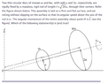
A diagram of a complex rigid body is given in the attached files having two discs of different sizes joined by a massless rod, statement of the question is given the picture in the attached files, I had doubt in one of the statements related to the rigid body given, that is its angular velocity of the center of mass of the whole system about z axis is w/5
Relevant Equations
for a point at a distance r from an axis of a rotating body , its velocity v=w x r
let point of contact of smaller disc with ground be P and
center of smaller disc be C and center of bigger disc be C'
angle POC= @
I assumed the angular velocity of the center of mass of the two discs about z axis to be w1
note that angular velocity of center of mass of both discs and center of anyone disc about z axis is same, you can verify that if you want, me after verifying it will use it to decrease the length of the my attempt section here
by applying Pythagoras theorem OP=5a, sin@=1/5
R=distance of center C from z axis = L*cos@, by some trigonometry
as the the discs are pure rolling on the ground, if we assume velocity of C of disc as V out of the plane of paper then the velocity of point P=V-wa=0( by condition for pure rolling)
V=wa
now by V=w1 x R
wa =w1 x L cos@
w1=5w/24
but the statement given further in the question that was cut out mentions the angular velocity about z axis as w/5
So I tried a more basic approach and got the answer , that approach is written further
if the the smaller disc rotates by angle 2pie in time t
then w= 2pie/t
t=2pie/w
as the smaller disc covers a circle of radius OP=5a for one rotation about the z axis, so the disc covers a circle of 2pie*5a
the smaller disc rotates by 2pie and covers distance 2pie*a for every complete turn, so it turns by 10 pie in one full rotation around z axis
in time 5*t so, w1 about z axis =2pie/5t
by this w1=w/5,
now i am in a dilemma why the first approach is wrong and the second one right?
 

Attachments

  • dbta.PNG
    dbta.PNG
    20.9 KB · Views: 112
  • Like
Likes Hamiltonian and Delta2
Physics news on Phys.org
  • #2
bhupesh said:
R=distance of center C from z axis = L*cos@,
How can we say R distance and L angular momentum has same dimension ?

As for going around the radius 5a circle
[tex]T=\frac{2\pi 5a}{a\omega}=\frac{2\pi}{\Omega}[/tex]
So
[tex]\Omega=\frac{\omega}{5}[/tex]
moment.jpg
 
Last edited:
  • #3
@bhupesh

I think your first approach is correct. So, ##\omega_1 = \frac{5}{24} \omega## is the correct relation. The mistake in your second approach is assuming that when the small disk rotates through an angle of ##2\pi##, the small disk rolls a distance of ##2 \pi a## on the flat surface.
 
Last edited:
  • Like
Likes Delta2 and bhupesh
  • #4
TSny said:
@bhupesh

I think your first approach is correct. So, ##\omega_1 = \frac{5}{24} \omega## is the correct relation. The mistake in your second approach is assuming that when the small disk rotates through an angle of ##2\pi##, the small disk rolls a distance of ##2 \pi a## on the flat surface.
then how much does it roll by when it rotates through 2pie*a
 
  • #5
anuttarasammyak said:
How can we say R distance and L angular momentum has same dimension ?

As for going around the radius 5a circle
[tex]T=\frac{2\pi 5a}{a\omega}=\frac{2\pi}{\Omega}[/tex]
So
[tex]\Omega=\frac{\omega}{5}[/tex]
L is the distance OC=root(24)*a
As for the approach you mentioned you mentioned, I have also written that as my second approach
I couldn't understand why the the first one is incorrect
 
  • #6
I see. To get speed of the center factor ##\frac{24}{25}## should be multiplied to speed of the tangential point. Slower because the wheel is inclined.
2021-06-06 13.21.44.jpg
 
Last edited:
  • #7
TSny said:
@bhupesh

I think your first approach is correct. So, ##\omega_1 = \frac{5}{24} \omega## is the correct relation. The mistake in your second approach is assuming that when the small disk rotates through an angle of ##2\pi##, the small disk rolls a distance of ##2 \pi a## on the flat surface.
I agree that the first approach is correct. That the second is wrong can be seen by considering ##r\rightarrow R##. The disc barely needs to rotate on its own axis at all to complete a revolution around the z axis, so ##\omega_1/\omega\rightarrow\infty##.
This also verifies your explanation of the error.

bhupesh said:
L is the distance OC=root(24)*a
You caused confusion by using uppercase L. In the problem statement, the distance is lowercase ##l## and ##\vec L## is used for angular momentum.
 
  • #8
haruspex said:
I agree that the first approach is correct. That the second is wrong can be seen by considering ##r\rightarrow R##. The disc barely needs to rotate on its own axis at all to complete a revolution around the z axis, so ##\omega_1/\omega\rightarrow\infty##.
This also verifies your explanation of the error.You caused confusion by using uppercase L. In the problem statement, the distance is lowercase ##l## and ##\vec L## is used for angular momentum.
what is small r that you mentioned , seeing your method
I came upon another reasoning that as @ tends to 0, then w1 tends to 0 , this discredits the first approach as w1=w/lcos@ according to the first approach
 
  • #9
anuttarasammyak said:
I see. To get speed of the center factor ##\frac{24}{25}## should be multiplied to speed of the tangential point. Slower because the wheel is inclined.
why does it get slower, it is both non intuitive and unlogical, could you explain why
 
  • Like
Likes Delta2
  • #10
When a wheel goes on a straight line ##v_c=v_t=a\omega##. when perpendicular wheel go around it is also.
But when an inclined wheel goes round, Center with smaller radius and tangential points with larger radius go around in same T. It means center has smaller speed than the tangential point. See my sketch attached to the previous post.
2021-06-06 16.56.04.jpg
 
Last edited:
  • #11
bhupesh said:
what is small r that you mentioned , seeing your method
I came upon another reasoning that as @ tends to 0, then w1 tends to 0 , this discredits the first approach as w1=w/lcos@ according to the first approach
Sorry, I used r instead of a in my working and forgot to switch back.
 
  • #12
anuttarasammyak said:
When a wheel goes on a straight line ##v_c=v_t=a\omega##. when perpendicular wheel go around it is also.
But when an inclined wheel goes round, Center with smaller radius and tangential points with larger radius go around in same T. It means center has smaller speed than the tangential point. See my sketch attached to the previous post.

I am not able to follow what you are saying. I assume you are discussing linear speed , not angular speed.

I explain the flaw in method 2 this way...
First, stop the disc rotating on the rod, so it slides along the surface instead.
Mark the point that stays in contact with the plane.
View the system from above. The disc appears as an ellipse, with the marked point always furthest from O. As the rod rotates once around the z axis, the ellipse does so, and also rotates around its own centre.
When we allow the disc to rotate on the rod, rolling on the plane, that rotation is additional to the rotation of the fixed disc described above.
It's the same issue as the difference between a solar day and a sidereal day.
 
  • #13
Yes I said linear speed there.

haruspex said:
View the system from above.
I do not catch your point but anyway tried to draw sketch of view from above. Is it alright ?
view from above.jpg
view from above2.jpg
 
Last edited:
  • #14
anuttarasammyak said:
When a wheel goes on a straight line ##v_c=v_t=a\omega##. when perpendicular wheel go around it is also.
But when an inclined wheel goes round, Center with smaller radius and tangential points with larger radius go around in same T. It means center has smaller speed than the tangential point. See my sketch attached to the previous post.View attachment 284072
center has smaller speed than tangential point , are you refferring to the the speed of the points on the rigid body barring rotation??, if yes then we were told in class that property of rigid body is that all points of a rigid body when considering translational motion have the same speed, your statement doesn't settle with this??
 
  • #15
anuttarasammyak said:
I do not catch your point but anyway tried to draw sketch of view from above. Is it alright ?https://www.physicsforums.com/attachments/284084
Nice diagram. But the effect is more obvious if you make the ellipse almost as big as the outer circle. As the ellipse rolls around the circle clockwise once, it only turns a fraction of a turn anticlockwise about its own centre.
 
  • #16
haruspex said:
But the effect is more obvious if you make the ellipse almost as big as the outer circle.
Before I redraw the sketch I would like to know was it already drawn as attached to post #10?
 
  • #17
haruspex said:
I am not able to follow what you are saying. I assume you are discussing linear speed , not angular speed.

I explain the flaw in method 2 this way...
First, stop the disc rotating on the rod, so it slides along the surface instead.
Mark the point that stays in contact with the plane.
View the system from above. The disc appears as an ellipse, with the marked point always furthest from O. As the rod rotates once around the z axis, the ellipse does so, and also rotates around its own centre.
When we allow the disc to rotate on the rod, rolling on the plane, that rotation is additional to the rotation of the fixed disc described above.
It's the same issue as the difference between a solar day and a sidereal day.
As i don't know difference between solar day and sidereal day, could you please tell me what's the issue in another way,
 
  • #18
bhupesh said:
are you refferring to the the speed of the points on the rigid body barring rotation??,
I am simply observing from above the motion of Center of wheel. I do not think property of rigid body matters.
 
  • #20
anuttarasammyak said:
Before I redraw the sketch I would like to know was it already drawn as attached to post #10?

Yes, it's like the lower diagram in post #10, but viewed from above.
 
  • #21
Thanks. So in this diagram Center draws small circle in time T. Contact points draw large circle in same time T. Center has smaller tangential speed and Contact points has larger tangential speed. They have different linear tangential speed but same angular speed ##\omega_1=\frac{a}{\sqrt{l^2+a^2}}\omega##.
Here what do I miss your point or flaw of method 2 for exact ##\omega_1## you said in post#12 ?
 
Last edited:
  • #22
bhupesh said:
then how much does it roll by when it rotates through 2pie*a
When the small disk rotates through an angle of ##2 \pi##, the center of the small disk moves through a distance of ##2 \pi a##. The distance that the small disk rolls on the surface is larger than ##2 \pi a## by a factor of ##\large \frac{r_p}{r_c }##, where ##r_c## is the distance of the center of the disk to the z-axis and ##r_p## is the distance of point ##p## to the z-axis. Here, ##p## is the point of contact between the disk and the surface. Since ##r_p = 5a## and ##r_c = \frac{24}{5} a##, ##\large \frac {r_p}{r_c} = \normalsize
\frac{25}{24}##.
 
Last edited:
  • #23
TSny said:
When the small disk rotates through an angle of ##2 \pi##, the center of the small disk moves through a distance of ##2 \pi a##. The distance that the small disk rolls on the surface is larger than ##2 \pi a## by a factor of ##\large \frac{r_p}{r_c }##, where ##r_c## is the distance of the center of the disk to the z-axis and ##r_p## is the distance of point ##p## to the z-axis. Here, ##p## is the point of contact between the disk and the surface. Since ##r_p = 5a## and ##r_c = \frac{24}{5} a##, ##\large \frac {r_p}{r_c} = \normalsize
\frac{25}{24}##.
If you would observe only the circumference of the small disc by visualise it to be rolling then it rolls 2pie*a on the circle of radius 5a fully in one roll, I think the center moves by a distance smaller than 2pie*a
 
  • #24
bhupesh said:
If you would observe only the circumference of the small disc by visualise it to be rolling then it rolls 2pie*a on the circle of radius 5a fully in one roll, I think the center moves by a distance smaller than 2pie*a
If a disk of radius ##a## rolls without slipping a distance ##d## along a straight line, then ##d = a \beta## where ##\beta## is the angle of rotation of the disk relative to the lab frame. This is no longer true if the disk rolls without slipping along an arc (unless the plane of the disk is perpendicular to the plane containing the arc).

For an intuitive way to see this, look at this old post. In that post, the disk and the circular arc lie in the same plane, and the disk rolls on the "inside" of the arc. It is shown there that when the disk rolls the same distance ##d## along the arc that it did along the straight line, then the angle ##\psi## that the disk rotates through is smaller compared to the rotation angle ##\beta## for the straight line. In particular, ##\psi = \beta - \theta##, where ##\theta## is the angle subtended by the circular arc. So for the arc, ##d > a \psi##.

If the disk rotates through one complete turn, ##\psi = 2 \pi## and ##d > 2 \pi a##. You can show that ##2 \pi a## gives the distance that the center of the disk travels when the disk makes one revolution relative to the lab frame.
 
  • #25
The statement of the problem says that the assembly is “set rolling without slipping on the surface so that its angular speed about the axis of the rod is ##\omega##". I think there might be some ambiguity in the definition of ##\omega## here.

You can think of the motion of the assembly as a superposition of two rotations. First, imagine the assembly rotating about the axis of the rod with angular velocity ##\boldsymbol \omega_0## while the assembly slips on the surface so that the rod remains stationary. Then add to this the correct amount of angular velocity ##\boldsymbol \Omega## about the z-axis to make the assembly roll without slipping on the surface.
1623122969806.png

The net angular velocity of the system is then ##\boldsymbol \omega^{\rm net} = \boldsymbol \omega_0 + \boldsymbol \Omega##. Since ##\boldsymbol \Omega## has a nonzero component along the rod of magnitude ##\Omega \sin \theta## in the direction opposite to ##\boldsymbol \omega_0 ##, the net angular speed of the assembly about the rod is ##\omega' = \omega_0 - \Omega \sin \theta##.

The ambiguity has to do with whether the ##\omega## stated in the problem is meant to be ##\omega_0## or meant to be ##\omega'##. You can show that ##\Omega = \frac{1}{5} \omega_0 = \frac{5}{24} \omega'##.

So, the result ##\Omega = \frac{1}{5} \omega## is consistent with taking ##\omega## to represent the quantity ##\omega_0##; whereas, the result ##\Omega = \frac{5}{24} \omega## is consistent with taking ##\omega## to be ##\omega'##.

You can also show that the speed of the center of the smaller disk is ##\omega' a## while the point of contact ##P## moves at speed ##\omega_0 a##.
 
  • #26
@bhupesh Here's a way to reconcile your two different methods of relating ##\omega## and ##\omega_1## in your first post.

##\omega## represents the angular speed of the disk "about the axis of the rod". Let ##\mathbf v_c## denote the velocity of the center of disk and let ##\mathbf v_p## represent the velocity of the point of the disk that is instantaneously in contact with the surface. The angular speed of the disk about the axis of the rod can be calculated as $$\omega =|\mathbf v_p - \mathbf v_c|/a$$
This formula for ##\omega## will give different results in different reference frames.

In the lab frame, ##v_p = 0## and ##v_c = \omega_1 r_c = \omega_1 \frac{24}{5} a##. So, the above formula for ##\omega## in the lab frame yields $$\omega^{\rm lab} = \frac{24}{5} \omega_1$$
But, if we interpret ##\omega## as the angular speed of the disk relative to the axis of the rod, then we need to use a reference frame in which the orientation of the rod remains fixed. This would be a reference frame rotating relative to the lab about the z-axis with angular speed ##\omega_1##. We'll call this the "rod frame". In this frame ##v_c = 0## and ##v_p = \omega_1 r_p = \omega_1 \cdot 5a##. Using ##\omega =|\mathbf v_p - \mathbf v_c|/a## in the rod frame yields $$\omega^{\rm rod} = 5 \omega_1$$
So, I would say that both of your methods in your first post are correct if you realize that in the first method your symbol ##\omega## represents ##\omega^{\rm lab}## while in the second method ##\omega## represents ##\omega^{\rm rod}##.

The problem statement apparently wants you to interpret ##\omega## as the rate of spin of the disk in the rod frame, ##\omega^{\rm rod}##. Then you get their result ##\omega_1 = \frac 1 5 \omega##. I think that interpreting ##\omega## this way is actually a natural way to interpret it for this problem. So, I shouldn't have implied that your second method was wrong. The two methods are correct as long as you interpret ##\omega## as ##\omega^{\rm lab}## in the first method and as ##\omega^{\rm rod}## in the second method.

In other problems, such as this problem, ##\omega^{\rm lab}## is of primary interest since it is used to calculate the rotational KE of the disk in the lab frame.

[To relate this post to post #25: ##\omega^{\rm lab}## of this post is the same as ##\omega'## in that post; whereas, ##\omega^{\rm rod}## here is the same as ##\omega_0## there. Also, ##\omega_1## here corresponds to ##\Omega## there.]
 
Last edited:

1. What is an existential dilemma on angular velocity?

An existential dilemma on angular velocity refers to the philosophical question of whether an object's angular velocity is a fundamental aspect of its existence or simply a construct of our perception and understanding of the object.

2. How does a complex rigid body impact this dilemma?

A complex rigid body, which is an object with multiple interconnected parts that maintain their relative positions and orientations, adds complexity to the question of angular velocity's role in an object's existence. It raises the question of whether the angular velocity of the individual parts is more important than the overall angular velocity of the entire body.

3. What are some practical implications of this dilemma?

The existential dilemma on angular velocity of a complex rigid body has implications in fields such as physics, engineering, and philosophy. It can impact our understanding of how objects move and interact with each other, as well as our perception of the world around us.

4. Is there a definitive answer to this dilemma?

There is no definitive answer to this philosophical question. It is a topic of ongoing debate and discussion among scientists and philosophers.

5. How can this dilemma be applied in real-world scenarios?

The concept of an existential dilemma on angular velocity can be applied in real-world scenarios, such as designing complex machinery or analyzing the movements of celestial bodies. It can also be used as a thought experiment to explore the nature of reality and our understanding of it.

Similar threads

  • Introductory Physics Homework Help
Replies
7
Views
1K
  • Introductory Physics Homework Help
Replies
3
Views
1K
  • Introductory Physics Homework Help
Replies
4
Views
830
  • Introductory Physics Homework Help
Replies
9
Views
1K
  • Introductory Physics Homework Help
10
Replies
335
Views
8K
Replies
7
Views
288
  • Introductory Physics Homework Help
Replies
2
Views
1K
  • Introductory Physics Homework Help
Replies
4
Views
1K
  • Introductory Physics Homework Help
Replies
18
Views
1K
  • Introductory Physics Homework Help
Replies
11
Views
1K
Back
Top