Experimental investigation of Faraday's Law of Induction

In summary: It's difficult to say without knowing more about your experiment, like what type of galvanometer or voltage sensor you are using.
  • #1
billyt_
20
11
Homework Statement
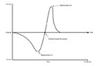
Does increasing the velocity of a magnet moving through a solenoid increase the EMF detected by a voltage sensor?
Relevant Equations
\varepsilon=-N \frac{\Delta \Phi}{\Delta t}
Looking at how the induced EMF is proportional to the rate of change of magnetic flux, intuitively it seems that if I increase the velocity of the magnet through the solenoid, i.e. drop it from a higher height, the EMF should increase as well. However, I am unsure if this is true and can't seem to find a derivation to check this. I want to make sure before I submit this to my lab technician as a practical to do.
 
Physics news on Phys.org
  • #2
Well, no replies yet and we don't want you to feel ignored! So, not answers to your questions, but this might help…

Can you sketch what you think a graph of emf vs. time might look like as the magnet moves through the coil at (for simplicity) constant velocity?

Can you tell us how you plan to measure the (possibly rapidly) changing emf?

For information, in-line Latex code here needs delimiting by two pairs of hash signs: ##\text {## LaTeX code ##}##

Then \varepsilon=-N \frac{\Delta \Phi}{\Delta t} comes out as
##\varepsilon=-N \frac{\Delta \Phi}{\Delta t}##

You can also enclose LaTeX code between 2 pairs of dollar signs to put the rendered code on its own line.

Before posting, check formatting using the Preview button (right end of menu bar) to toggle between edit and preview modes.

Also, for the emf symbol, you might prefer \mathscr E which renders as ##\mathscr E##. My school physics teacher called it 'curly E'; later I found out it is more correctly called 'script E'.

Edit - typo' corrected.
 
  • Like
Likes BvU and billyt_
  • #4
Steve4Physics said:
Well, no replies yet and we don't want you to feel ignored! So, not answers to your questions, but this might help…

Can you sketch what you think a graph of emf vs. time might look like as the magnet moves through the coil at (for simplicity) constant velocity?

Can you tell us how you plan to measure the (possibly rapidly) changing emf?

For information, in-line Latex code here needs delimiting by two pairs of hash signs: ##\text {## LaTeX code ##}##

Then \varepsilon=-N \frac{\Delta \Phi}{\Delta t} comes out as
##\varepsilon=-N \frac{\Delta \Phi}{\Delta t}##

You can also enclose LaTeX code between 2 pairs of dollar signs to put the rendered code on its own line.

Before posting, check formatting using the Preview button (right end of menu bar) to toggle between edit and preview modes.

Also, for the emf symbol, you might prefer \mathscr E which renders as ##\mathscr E##. My school physics teacher called it 'curly E'; later I found out it is more correctly called 'script E'.

Edit - typo' corrected.
Thanks a lot!
- I have attached a photo of a graph showing the change in voltage over time. You can see that the current reverses as the magnet passes through the halfway point and ∴ the velocity also reverses. However, I am simply looking at the magnitude of the Voltage, so what is really relevant for me is the y-coords of the maximum points. Theoretically, if the velocity increases the magnitude should also increase, but the area under the curve will remain the same as the "pulse" becomes shorter to account for cons. of energy.
- I was planning on using either a galvanometer or a voltage sensor linked up to a scope to show the changing emf.
- also thanks for the latex tips
 

Attachments

  • drop-a-magnet-through-a-solenoid-59.544f5fa.jpg
    drop-a-magnet-through-a-solenoid-59.544f5fa.jpg
    13.1 KB · Views: 62
  • Like
Likes Steve4Physics and Charles Link
  • #5
billyt_ said:
I have attached a photo of a graph showing the change in voltage over time.
Good. You will note the negative and positive parts of your graph have different sizes/shapes. Can you explain that? (And at the same time answer your question (Post#1) about the relationship between induced emf and velocity?)

billyt_ said:
You can see that the current reverses as the magnet passes through the halfway point
You mean the induced emf reverses (but if there is a circuit allowing current to flow, it's true of current too).

billyt_ said:
However, I am simply looking at the magnitude of the Voltage, so what is really relevant for me is the y-coords of the maximum points.
Edit. Comment deleted! There are 2 emf maxima - one is positive and one is negative. Do they have the same values? Which one do you want!?

billyt_ said:
Theoretically, if the velocity increases the magnitude should also increase, but the area under the curve will remain the same as the "pulse" becomes shorter to account for cons. of energy.
Maybe (or maybe not) the areas are the same but I don't see what conservation of energy has to do with it.

billyt_ said:
- I was planning on using either a galvanometer or a voltage sensor linked up to a scope to show the changing emf.
If you are planning on dropping a magnet through a coil, are you certain the response-time of a galvanameter would be adequate? Maybe you could estimate a ball-park value of the required response time using some assumptions and simple kinematics.

A conventional 'scope would briefly give a waveform similar to your graph, but would then vanish! You need a storage scope or maybe a data-logger to get a decent emf measurement.

So some careful thought about the experimental design and equipment limitations is needed.

But first, make sure you first have a clear obective for your investigation. You should know what your are trying to do - e.g. test some specific quantitative hypothesis.
 
  • Like
Likes BvU, billyt_ and Charles Link
  • #6
Steve4Physics said:
Good. You will note the negative and positive parts of your graph have different sizes/shapes. Can you explain that? (And at the same time answer your question (Post#1) about the relationship between induced emf and velocity?)You mean the induced emf reverses (but if there is a circuit allowing current to flow, it's true of current too).Edit. Comment deleted! There are 2 emf maxima - one is positive and one is negative. Do they have the same values? Which one do you want!?Maybe (or maybe not) the areas are the same but I don't see what conservation of energy has to do with it.If you are planning on dropping a magnet through a coil, are you certain the response-time of a galvanameter would be adequate? Maybe you could estimate a ball-park value of the required response time using some assumptions and simple kinematics.

A conventional 'scope would briefly give a waveform similar to your graph, but would then vanish! You need a storage scope or maybe a data-logger to get a decent emf measurement.

So some careful thought about the experimental design and equipment limitations is needed.

But first, make sure you first have a clear obective for your investigation. You should know what your are trying to do - e.g. test some specific quantitative hypothesis.
I see - there is a lot to think about!
Thanks a lot for the tips and I will refer back to this for further guidance in the experiment. I can see that I still have a bit of research to do!
Thanks a lot
 
  • #7
Note: Since EMF ## \mathcal{E}=-d \Phi/dt ##, and the flux reaches a maximum as the voltage or EMF goes to zero, (i.e. ## \mathcal{E}=- d \Phi /dt=0 ## at the maximum ## \Phi ##), and then the flux decreases again to zero as the magnet moves far away from the ring, by looking at ##| \int \mathcal{E} \, dt | =|\Delta \Phi | ## for these two regions, they do indeed have equal areas.

Edit: Note that the area under either region of the curve of voltage vs. time allows for a simple measurement of the flux ## \Phi ## across the center (interior cross section) of the magnet. If the loop of wire is much larger than the magnet, the reading will not be accurate, as the flux looping around outside the magnet will make the reading (area under the curve) lower than the actual value of the flux across the interior cross section of the magnet.
 
Last edited:
  • Like
Likes billyt_ and Steve4Physics

1. What is Faraday's Law of Induction?

Faraday's Law of Induction states that a changing magnetic field will induce an electric current in a conductor. This phenomenon was discovered by scientist Michael Faraday in the 19th century and is a fundamental principle in electromagnetism.

2. How is Faraday's Law of Induction experimentally investigated?

To experimentally investigate Faraday's Law of Induction, a setup involving a magnet, a coil of wire, and a galvanometer is typically used. The magnet is moved in and out of the coil, creating a changing magnetic field which induces a current in the wire. The galvanometer measures the strength and direction of the current.

3. What are the factors that affect the induced current in Faraday's Law of Induction?

The induced current in Faraday's Law of Induction is affected by the strength of the magnetic field, the rate at which the magnetic field changes, and the number of turns in the coil. The material of the conductor and its resistance also play a role in the induced current.

4. How is Faraday's Law of Induction applied in real-world applications?

Faraday's Law of Induction is applied in many real-world applications, such as generators, transformers, and electric motors. It is also used in wireless charging technology and in the operation of many electronic devices.

5. What are some common misconceptions about Faraday's Law of Induction?

One common misconception is that Faraday's Law of Induction only applies to stationary magnets and conductors. In reality, it also applies to moving magnets and conductors, as long as there is a relative motion between them. Another misconception is that the induced current is caused by the magnetic field itself, when in fact it is the changing magnetic field that induces the current.

Similar threads

  • Introductory Physics Homework Help
Replies
7
Views
78
  • Introductory Physics Homework Help
Replies
3
Views
151
  • Introductory Physics Homework Help
Replies
1
Views
158
  • Introductory Physics Homework Help
Replies
1
Views
215
  • Introductory Physics Homework Help
Replies
1
Views
133
  • Introductory Physics Homework Help
Replies
3
Views
1K
  • Introductory Physics Homework Help
Replies
3
Views
3K
  • Introductory Physics Homework Help
Replies
1
Views
695
  • Introductory Physics Homework Help
Replies
11
Views
2K
  • Introductory Physics Homework Help
Replies
1
Views
711
Back
Top