- #1
Kashmir
- 465
- 74
Thread moved from the technical forums to the schoolwork forums
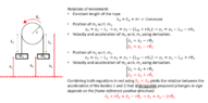
What is the initial acceleration of mass 5M .The pulleys are ideal and the string inextensible.

My attempt-
2Mg-T=2Ma (for 2M)
T=Ma (for M)
Solving we get T=2Mg/3
T-N=5MA (for 5M)
N=2MA (for 2M)
Solving we get A=2g/21
but the given ans. is 2g/23
My attempt-
2Mg-T=2Ma (for 2M)
T=Ma (for M)
Solving we get T=2Mg/3
T-N=5MA (for 5M)
N=2MA (for 2M)
Solving we get A=2g/21
but the given ans. is 2g/23