Finding exact 3d coordinates in a falling pipe system with corners

In summary: Then we get $\mathbf x_2 = (x_1, y_1, z_2)$.Finally, we get $x_2 = x_1$, $y_2 = y_1$, $z_2 = z_1 + w_z$.In summary, to calculate the coordinates of the end point of the corner in a falling pipe system with variable lengths and angles, we can use the following formula:$x_2 = x_1$, $y_2 = y_1$, $z_2 = z_1 + w_z$, where $w_z$ is the vertical component of the vector $\mathbf w$ with length $w$ and angle
  • #1
BrentK
21
0
Hi All.
I'm new here so I hope you will bear with me and please tell me if this is out of context or in the wrong part of the forum.

I am trying to programm a falling pipe system with corners in ArchiCAD (GDL).
I have been programming in different languages for a while now, but new to 3D vector coordinate programming and never really had to face complex mathmatical challenges like this.

I am hoping you Maths experts will be able to help me with this as I have now spent days trying to get it right and am slowly going crazy!

OK here we go. Hope its not too complicated to explain...

The falling pipe programm includes pipes at varaible lengths, followed by corners or bends at variable angles, in the same fall slope.
Each item (pipe or corner) starts at a coordinate point, then with the given slope and angle calculates the exate end point coordinates in x,y and z, to connect the next item to.
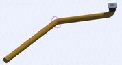
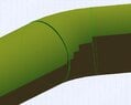
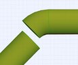
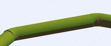
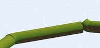
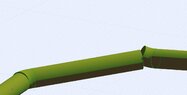
The normal straight pipes are no problem, but I am having trouble calculating the exact end point of the corners.

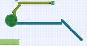
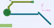
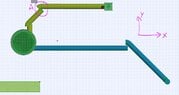
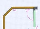
Here are images showing the current results of my programm (Notice the offset of the last connecting pipe to the 45 degree corner piece)

View attachment 8572

View attachment 8573

Here is the code of the corner item. I tried to comment it as good as possible and hope that it is self explanatary. If something is unclear please feel free to ask me.

Just to clarify, it is the returned coordinates that are not quite right RET_X,RET_Y and RET_Z. I suspect it has to do with the fall in the corner that i can't quite figure out.

Code:
!=======================================================================

		!Here are the dynamic variables, normally provided by program code or user: ... (HEL = Horizontal Elbow...or corner)

!=======================================================================

			HEL_Slope	= -10														! Slope in percent (10 percent is unrealistic but magnifies the angle for testing purposes)
			Y_ROT_S		= -90														! Starting rotation in the Y Axis (used to set the rotation position matching the preceding object(pipe))
			X_ROT_S		= 90														! Rotation Direction in the X-Axis (Provides the direction in which the following object (pipe)will continue in)
			HEL_D		= 0.1														! Dimension of the drainpipe in m (in this case 10cm)
			ELBOW_R		= HEL_D														! Radius of the corner is the same as the dimension of the pipe
			HEL_ROT		= 45														! Angle of the corner (In this case 45 degrees)
!=======================================================================

		!Calculate parameters  

!=======================================================================

			HEL_Slopedegree=ATN(HEL_SLOPE/100)									!Turn the percentage slope into slope in degrees (percentage is given because it is standard pipe slope unit)
!=======================================================================

		!Apply Rotational values

!=======================================================================

			ROTX X_ROT_S													!Rotate the corner in the X Axis
			ROTZ -(HEL_Slopedegree)												!Rotate the corner in the Z Axis (continuing slope of the pipe system)
			ROTY Y_ROT_S														!Rotate the corner in the Y Axis
!=======================================================================

		!Draw the corner 

!=======================================================================		ELBOW ELBOW_R,HEL_ROT,HEL_D/2											!Call syntax: ELBOW [Radius of corner],[Angle size to draw],[Radius of pipe]

!=======================================================================

		! Calculate the exact end coordinates of the corner to place the next piece of the pipe line
		! RET_X,RET_Y and RET_Z are the positions that the macro will return to the original programm call
		! Here is where I am having problems ! :)!=======================================================================

		!New X and Y coordinates:
		!------------------------
		!Based on the following theory i try and find the new x and y positions

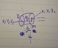
		!if the centre of the answer circle is (h,k),angle θ,and radius r,then position of point is
		!(h+rcosθ,k+rsinθ)

			IF X_ROT_S < 0 THEN
				RET_X=-(HEL_D*COS(HEL_ROT))
				RET_Y=HEL_D-(HEL_D*SIN(HEL_ROT))
			ELSE
				RET_X=-(HEL_D*COS(HEL_ROT-.3))
				RET_Y=-HEL_D+(HEL_D*SIN(HEL_ROT))
			ENDIF

		!New Z coordinate:
		!------------------------
		!To find the difference in height at the given pipe slope I try using pythagoras theory to first find the 
		!distance "C" between the old and new coordinate (a2+b2=c2)

			A=HEL_X-RET_X
			B=HEL_Y-RET_Y
			C=SQR(A^2+B^2)

			RET_Z = C * SIN(HEL_Slopedegree)
Thanks to anyone who can relieve the current pressure on my brain and help me finally figure this out!
 

Attachments

  • corner1.JPG
    corner1.JPG
    98.3 KB · Views: 82
  • corner2.JPG
    corner2.JPG
    33.7 KB · Views: 85
Mathematics news on Phys.org
  • #2
Maybe I need to put this to you guys as a pure mathematical question...

Given coordinate x1,y1,z1, how do I calculate x2,y2,z2?
Given the folowing
Diameter of the pipe is D,
The radius of the corner is R,
Angle of the corner is θ1
Angle of the slope is θ2

View attachment 8575
 

Attachments

  • corner3.JPG
    corner3.JPG
    23.2 KB · Views: 76
  • #3
Suppose the first pipe goes down from $\mathbf x_0 = (x_0,y_0,z_0)$ to $\mathbf x_1 = (x_1,y_1,z_1)$.
Then its downward vector is $\mathbf v = (v_x, v_y, v_z) = \mathbf x_1 - \mathbf x_0 = (x_1-x_0, y_1-y_0, z_1-z_0)$.
The length of the downward vector is $v = \sqrt{v_x^2 + v_y^2 + v_z^2}$.
And its downward slope is $\theta_2 = \arcsin \frac {v_z}{v}$.

Suppose the second pipe must go down with a vector $\mathbf w =(w_x,w_y,w_z)$ that has length $w$.
And suppose that the pipes must make and angle $\theta_1$ with each other over a radius $R$.
Then $\mathbf x_2 = (x_2, y_2, z_2) = \mathbf x_1 + R\tan\frac{\theta_1}2\left(\frac{\mathbf v}{v}+\frac{\mathbf w}{w}\right)$.
 
  • #4
Hi Klaas,
Thanks so much for your reply.
Unfortunately I am no math genius :(
Im not quite following your theory. Pipe1 that you mentioned would be the straight pipe leading up to the corner?
Then the second pipe vector would be the starting point of the second straight point after the corner?

would it be possible to provide a sketch to better understand where the vectors are that you are referring to?

Sorry for my incompetence... trying hard to get a grip on this stuff

Regards
Brent
 
  • #5
Here's the picture:
\begin{tikzpicture}[>= stealth', thick]
%preamble \usetikzlibrary{arrows}
\coordinate[label=above:$\mathbf x_0$] (x0) at (0,0);
\coordinate[label=above:$\mathbf x_1$] (x1) at (-6,-2);
\coordinate (r) at (-5,-5);
\coordinate (m) at (-7.5,-2.5);
\coordinate[label=left:$\mathbf x_2$] (x2) at (-8,-4);
\coordinate[label=left:$\mathbf x_3$] (x3) at (-9,-7);

\draw[help lines] (x1) -- +(3,0);
\draw (x1) +(1.1,0) arc (0:atan2(1,3):1.1) +(.5,-.15) node {$\theta_2$};
\draw[blue,ultra thick,->] (x0) -- node[above] {$\mathbf v$} (x1);
\draw (x1) -- (r) -- node[below] {$R$} (x2);
\draw[help lines] (x1) -- node[above,xshift=-8] {$R\tan \frac{\theta_1}2$} (m) -- (x2);
\draw[help lines] (r) -- (m);
\draw (r) +({atan2(3,-1)}:1.1) arc (atan2(3,-1):atan2(1,-3):1.1) +(.5,0.2) node {$\theta_1$};
%\path (r) node at +(-.5,.5) {$\theta_1$};
\draw[blue,ultra thick,->] (x2) -- node
{$\mathbf w$} (x3);
\end{tikzpicture}

The formulas I gave will work whether the pipes are 'falling down', or are going into any arbitrary direction.​
 
  • #6
Thanks Klaas!
I'm way out of depth here. Sorry :(

So backing up a little, What would be the formula to find the end point displacements of x1,y1 and z1 from x0,y0,z0 of vector v, with known parameters θ2 and length v?

I was using:
y1 = y0-(v * COS(θ1))
x1 = x0-(v * SIN(90-θ2))
z1= z0-(SIN(-θ2)*v)

where θ1 was the angle of the pipe in relation to the y-axis and θ2 the fall slope of the pipe.

This seemed to work when θ1 was -90deg (as shown in the images above) but if it is say -45deg then it is not working :(View attachment 8576If you can help me in these terms, so i can find the separate coordinates, then I would be extremely happy...otherwise i may have to give up :(

Thank you so much for your time and patience
Regards
Brent
 

Attachments

  • corner4.JPG
    corner4.JPG
    51.6 KB · Views: 78
  • #7
BrentK said:
Thanks Klaas!
I'm way out of depth here. Sorry :(

So backing up a little, What would be the formula to find the end point displacements of x1,y1 and z1 from x0,y0,z0 of vector v, with known parameters θ2 and length v?

I was using:
y1 = y0-(v * COS(θ1))
x1 = x0-(v * SIN(90-θ2))
z1= z0-(SIN(-θ2)*v)

where θ1 was the angle of the pipe in relation to the y-axis and θ2 the fall slope of the pipe.

This seemed to work when θ1 was -90deg (as shown in the images above) but if it is say -45deg then it is not working :(

If you can help me in these terms, so i can find the separate coordinates, then I would be extremely happy...otherwise i may have to give up :(

Thank you so much for your time and patience
Regards
Brent

That's an unconventional choice for θ1. Anyway, if you mean what I think you mean with θ1, we have:
\begin{cases}
x_1= x_0-v\sin\theta_1\cos\theta_2 \\
y_1=y_0+v\cos\theta_1\cos\theta_2 \\
z_1=z_0-v\sin\theta_2
\end{cases}
 
  • #8
Klaas you are a genius!
Thank you so much, that works perfectly... had to adjust a little to:

x1=x0+vsinθ1cosθ2
y1=y0-vcosθ1cosθ2
z1=z0−vsinθ2...Dont ask me why but that works perfectly now!

Would it be too much to ask for similar formulas to get the end point of the corner? :) :)

And would you have any online documentation that I could take a look at to try and understand how you got that solution? I would love try and be able to understand that.

Many Many thanks I am very grateful to you! Next time you visit switzerland let me know. I shout you out for dinner :)But only if i get the coordinate formulas for the corner :) :) :)

Thanks again
Regards
Brent
 
  • #9
BrentK said:
Klaas you are a genius!
Thank you so much, that works perfectly... had to adjust a little to:

x1=x0+vsinθ1cosθ2
y1=y0-vcosθ1cosθ2
z1=z0−vsinθ2

...Dont ask me why but that works perfectly now!

It means that your θ1 is with respect to the negative y-axis, while I had assumed the positive y-axis.
BrentK said:
Would it be too much to ask for similar formulas to get the end point of the corner? :) :)

The angle θ1 that you mentioned previously (different from that last θ1 I presume?), is not sufficient to find it.
There are infinitely many solutions with only that angle.
That's why I introduced the vector $\mathbf w$ to uniquely identify in which direction the second pipe is supposed to be directed.
Does that work for you?
Or do you have another angle to identify the direction of the second pipe, similar to how you identified the direction of the first pipe?

BrentK said:
And would you have any online documentation that I could take a look at to try and understand how you got that solution? I would love try and be able to understand that.

It's a variant of the spherical coordinate system:
https://en.wikipedia.org/wiki/Spherical_coordinate_system

Your angles are different than the standard spherical coordinates though, meaning switching around some cosines, sines, and signs.

BrentK said:
Many Many thanks I am very grateful to you! Next time you visit switzerland let me know. I shout you out for dinner :)

But only if i get the coordinate formulas for the corner :) :) :)

Thanks again
Regards
Brent
 
  • #10
Hi Klaas,
So given the following diagram:

View attachment 8578

X1,Y1,Z1,θ1,θ2 and R are known parameters

θ1 is the angle of the corner
θ2 is the falling slope in the z axisAfter reading the wikipedia link you sent and trying to apply the last formluars you gave i tried:

X2=X1-R*SIN(θ1)*COS(θ2)
Y2=Y1-R*SIN(θ1)*SIN(θ2)
Z2=Z1-RCOS(θ2)

And Also:

X2=X1-R*SIN(θ1)*COS(θ2)
Y2=Y1-R*COS(θ1)*COS(θ2)
Z2=Z1-RCOS(θ2)The later giving this result:

View attachment 8579

I also tried switching the angles over
Unfortunately nothing worked.It looks like the Z axis is good. can't tell for sure until i get the x and y coordinates right though.

Can you help me out on this basis?
Thanks!

PS in the above applied example,
θ1 is 45deg
θ2 is 2 percent fall
R is 0.1m
 

Attachments

  • corner3.JPG
    corner3.JPG
    23.2 KB · Views: 68
  • Unbenannt.JPG
    Unbenannt.JPG
    21.9 KB · Views: 68
Last edited:
  • #11
Hi Brent,

I have some trouble understanding what your angles θ1 and θ2 are exactly in your drawing.
They are different from the angles that we used to determine the direction vector of the first pipe aren't they?
There we had that θ1 was the horizontal angle with the negative y-axis (similar to longitude).
And θ2 was the downward angle (similar to latitude down).

Can it be that in the elbow drawing:
- θ1 is a horizontal angle as well, and represents the increase in the original θ1?
- θ2 represents the increase in the original θ2?

If so, I'd like to call them $\Delta θ_1$ respectively $\Delta θ_2$ to distinguish them from the previously used angles, and to indicate that they are changes in those angles.
Before I set up any formulas, can you clarify?
 
  • #12
Hi Klaas,
Sorry for the lack of clarity.

Klaas van Aarsen said:
Can it be that in the elbow drawing:
- θ1 is a horizontal angle as well, and represents the increase in the original θ1?

Yes that would be correct...could also be a decrease, if the corner goes in the other direction. But let's just get it right for this example, then i hope to be able to figure out how I can adjust.
Klaas van Aarsen said:
- θ2 represents the increase in the original θ2?

This is the same axis, but stays the same value, so no increase. it would be the same as the original θ2. (Slope fall of the piping system which is constant through all elements)

Klaas van Aarsen said:
If so, I'd like to call them $\Delta θ_1$ respectively $\Delta θ_2$ to distinguish them from the previously used angles, and to indicate that they are changes in those angles.
Before I set up any formulas, can you clarify?

Sure that would make sense to give these angles other names.

Thanks for your help!

Regards
Brent
 
Last edited:
  • #13
Hmm... this gets a little complicated...
I get:
$$\mathbf x_2 = \mathbf x_1 + \frac R{\|\mathbf{\hat v} \times \mathbf{\hat w}\|} \Big((\mathbf{\hat v} \times \mathbf{\hat w})\times(\mathbf{\hat v} - \mathbf{\hat w})\Big)
$$
Or split up:
\begin{cases}v_1 = \sin\theta_1\cos\theta_2 \\ v_2=-\cos\theta_1\cos\theta_2 \\ v_3 = -\sin\theta_2\end{cases}
\begin{cases}w_1 = \sin(\theta_1+\Delta\theta_1)\cos\theta_2 \\ w_2=-\cos(\theta_1+\Delta\theta_1)\cos\theta_2 \\ w_3 = -\sin\theta_2\end{cases}
\begin{cases}c_1 = v_2w_3-v_3w_2 \\ c_2=v_3w_1-v_1w_3 \\ c_3 = v_1w_2 - v_2w_1\end{cases}
$$c = \sqrt{c_1^2+c_2^2+c_3^2}$$
\begin{cases}d_1 = v_1-w_1 \\ d_2=v_2-w_2 \\ d_3 = v_3 - w_3\end{cases}
\begin{cases}e_1 = c_2d_3-c_3d_2 \\ e_2=c_3d_1-c_1d_3 \\ e_3 = c_1d_2 - c_2d_1\end{cases}
\begin{cases}x_2 = x_1 + \frac Rc e_1 \\ y_2 = y_1 + \frac Rc e_2 \\ z_2 = z_1 + \frac Rc e_3\end{cases}
 
  • #14
Hmmm that is complex.
Did you calculate from the start of the first pipe?
If so that's not necessary.
I have the coirdinates of the endpoint of that point, so we can forget that pipe completely and just calculate the end point of the corner given any x1, y1,z1.
Does that make it easier?
 
  • #15
Hi Klaas,
Sorry to bother you again, just following up...
I am trying hard to apply your formula. What I don't understand is why it is necessary to use the angles of the previous pipe ( Δθ1 ). ... This is going to make my programm coding rather complicated, particularly if i want to use this macro object in a different situation, eg as starting element without any pipe leading up to it.

w1=sin(θ1+Δθ1)cosθ2
w2=−cos(θ1+Δθ1)cosθ2
w3=−sinθ2

Do I really need to know what angle the previous pipe is at? Can we not just start at the coordinates at the end of that pipe (which are the same as the coordinates at the start of this corner) and calculate from there (x1,y1,z1) to x2,y2,z2... so totally irrespective of any preceding element.
It shouldn't be too different from the formula from the pipe( I am guessing) except the length would be the distance around the radius R instead of in a straight line...? But i just can't get it right

Could you possibly give me some feedback on that thought? Or am i completely wrong in my assumption that Δθ1 is the angle from the previous pipe element? ( Also quite possible considering my math skills :) )

Thanks for all your help!
Regards
Brent
 
  • #16
BrentK said:
Hi Klaas,
Sorry to bother you again, just following up...
I am trying hard to apply your formula. What I don't understand is why it is necessary to use the angles of the previous pipe ( Δθ1 ). ... This is going to make my programm coding rather complicated, particularly if i want to use this macro object in a different situation, eg as starting element without any pipe leading up to it.

Do I really need to know what angle the previous pipe is at? Can we not just start at the coordinates at the end of that pipe (which are the same as the coordinates at the start of this corner) and calculate from there (x1,y1,z1) to x2,y2,z2... so totally irrespective of any preceding element.
It shouldn't be too different from the formula from the pipe( I am guessing) except the length would be the distance around the radius R instead of in a straight line...? But i just can't get it right

Could you possibly give me some feedback on that thought? Or am i completely wrong in my assumption that Δθ1 is the angle from the previous pipe element? ( Also quite possible considering my math skills :) )

Thanks for all your help!
Regards
Brent

What we need is the direction of the second pipe however we identify it.
And we need the direction and end point of the first pipe as well to figure out how to fit the elbow.

The input for the formulas is:
  • Direction of pipe 1, currently identified by $\theta_1$, the horizontal angle with the negative y-axis, and $\theta_2$, the falling angle.
  • Direction of pipe 2. currently identified by $\theta_1+\Delta\theta_1$, the horizontal angle with the negative y-axis, and $\theta_2$, the same falling angle as pipe 1.
    $\theta_1$ is still the horizontal angle of pipe 1 here, and $\Delta\theta_1$ is the increase in that angle.
    Alternatively we might identify the horizontal angle for instance by $\theta_{1, pipe 2}$, as long as there is no confusion with the $\theta_1$ that belongs to pipe 1.
  • The end point of pipe 1, identified by $\mathbf x_1 = (x_1,y_1,z_1)$.
The output of the formulas is:
  • The starting point of pipe 2, identified by $\mathbf x_2 = (x_2,y_2,z_2)$.

I'm trying in particular to keep the meaning of the symbols unique.
Alternatively, we could also identify the direction of pipe 1 by $\theta_{1,pipe 1}$ and the direction of pipe 2 by $\theta_{1,pipe 2}$.
Would that help you?
Or do you have a different way in mind to identify how pipe 2 is supposed to be oriented?
 
  • #17
Ok Klaas , Now I see.
I think i can work with that.
I'll try.
Thanks
 
  • #18
Hi Klaas,
Unfortunately I am still struggling with this. I have tried using your given formula, and also tried in various different ways altering the +- to see what results I get.
Your formula applied to this object and pipe systems is giving me this result:

View attachment 8597

Is it possible that there is some error in the formula?

Here is what I am using with the actual values for corner "A" put into the formula instead of variables:

Code:
		v1=SIN(45)*COS(-2)
		v2=-COS(45)*COS(-2)
		v3=-SIN(-2)

		w1=SIN(45+-90)*COS(-2)
		w2=-COS(45+-90)*COS(-2)
		w3=-SIN(-2)

		c1=v2*w3-v3*w2
		c2=v3*w1-v1*w3
		c3=v1*w2-v2*w1

		c=SQR(c1^2+c2^2+c3^2)

		d1=v1-w1
		d2=v2-w2
		d3=v3-w3

		e1=c2*d3-c3*d2
		e2=c3*d1-c1*d3
		e3=c1*d2-c2*d1

		x2=((0.1/2)/c)*e1
		y2((0.1/2)/c)*e2
		z2=((0.1/2)/c)*e3

The actual returned values are:

x1 = 0
y1 = -0.0706683
Z1 = 0.0019988

Any ideas? (Thinking)
 

Attachments

  • Unbenannt.JPG
    Unbenannt.JPG
    56.7 KB · Views: 48
  • Unbenannt1.JPG
    Unbenannt1.JPG
    58.5 KB · Views: 51
  • Unbenannt2.JPG
    Unbenannt2.JPG
    59.7 KB · Views: 54
  • #19
I can't match your angles with your picture.
Code:
                v1=SIN(45)*COS(-2)
		v2=-COS(45)*COS(-2)
		v3=-SIN(-2)

		w1=SIN(45+-90)*COS(-2)
		w2=-COS(45+-90)*COS(-2)
		w3=-SIN(-2)
Which pipes are these supposed to be?
I don't see a 90 degree connection anywhere.

My best guess based on your earlier picture, is that it should be:
Code:
                v1=SIN(90)*COS(-2)
		v2=-COS(90)*COS(-2)
		v3=-SIN(-2)

		w1=SIN(90+45)*COS(-2)
		w2=-COS(90+45)*COS(-2)
		w3=-SIN(-2)
Would that fix your problem?

Btw, I notice that you have [M]c=SQR(c1^2+c2^2+c3^2)[/M].
Is that SQR a square or a square root?
It has to be a square root, which is usually denoted as SQRT.

Furthermore, you have:
Code:
		x2=((0.1/2)/c)*e1
		y2((0.1/2)/c)*e2
		z2=((0.1/2)/c)*e3
I seem to be missing (x1,y1,z1) in there. Or did you pick them to be zero?
 
  • #20
Hi Klaas, Sorry I've been on the road the last couple of days.
Just picked this up and yes your guess was pretty much right.

This seems to give me the right coordinates:

Code:
			v1=SIN(-90)*COS(2)
			v2=-COS(-90)*COS(2)
			v3=-SIN(2)
	
			w1=SIN(45-90)*COS(2)
			w2=-COS(45-90)*COS(2)
			w3=-SIN(2)

To answer your questions... I hope :)

Which pipes are these supposed to be?
I don't see a 90 degree connection anywhere.

This is where i was getting my angles from:

View attachment 8613

Btw, I notice that you have c=SQR(c1^2+c2^2+c3^2).
Is that SQR a square or a square root?
It has to be a square root, which is usually denoted as SQRT.

... The Program coding in GDL uses "SQR" for Square root, so should be good.

I seem to be missing (x1,y1,z1) in there. Or did you pick them to be zero?

Well actually I am saving the end point of an object as the current (local) coordinate each time i place an object, so the next object gets placed at 0,0,0

This may be helpful to better explain out of the gdl Manual:

In GDL, all the geometric elements are linked strictly to the local coordinate system. GDL uses a right-handed coordinate system. For example, one corner of a block is in the origin and its sides are in the x-y, x-z and y-z planes.

Placing a geometric element in the desired position requires two steps. First, move the coordinate system to the desired position. Second, generate the element. Every movement, rotation or stretching of the coordinate system along or around an axis is called a transformation
 

Attachments

  • Unbenannt.JPG
    Unbenannt.JPG
    42.6 KB · Views: 46
  • #21
Unfortunately the new calculations have aired a new challenge.
It seems I am not quite getting the X rotation quite right.

The calculated end coorddinate from your formula now looks good, but it seems i haven't taken everything into consideration in rotating the corner correctly.

This is the result using your new formula for the "endpoint" of the elbow...which is seen actually as the starting point of the next pipe. WHich is correct. Using a rotation angle in the X-axis of 90degrees I get this:

View attachment 8614

To Illustrate how this rotation in the x-axis is working, here are some axamples. The first is rotation 0degrees, the second 45degrees:

View attachment 8615

View attachment 8616

By trial and error I get it about right on this corner by increasing by 4degrees, So 94degrees is nearly right. (NOTE... I nearly forgot... In these examples i was using a fall slope of 10 degress instead of 2degrees to make it show more clearly, so "94 degrees" would be nearly right with a fall slope of 10 dgerees , not 2 as in your last formula)

Notice though, using the same corner code, the second corner is further out...

What do you think. Is this going to be too hard to manage or do you think you may be able to find a solution to calculate the correct X-axis rotation angle? (The same parameters are available to calculate with as in the previous example...(Whew) (Smile)
 

Attachments

  • Unbenannt.JPG
    Unbenannt.JPG
    75.2 KB · Views: 52
  • Unbenannt1.JPG
    Unbenannt1.JPG
    71.6 KB · Views: 51
  • Unbenannt45.JPG
    Unbenannt45.JPG
    93.3 KB · Views: 45
Last edited:

1. How do you calculate the exact 3d coordinates in a falling pipe system with corners?

The exact 3d coordinates in a falling pipe system with corners can be calculated using a mathematical formula that takes into account the length, width, and height of the pipe, as well as the angle of the corners and the velocity of the falling object.

2. What tools or equipment are needed to find the exact 3d coordinates in a falling pipe system with corners?

To find the exact 3d coordinates in a falling pipe system with corners, you will need a measuring tape or ruler to determine the dimensions of the pipe, a protractor to measure the angle of the corners, and a stopwatch to measure the velocity of the falling object.

3. Can the exact 3d coordinates be determined without using mathematical calculations?

No, mathematical calculations are necessary to determine the exact 3d coordinates in a falling pipe system with corners. Without these calculations, the coordinates will not be accurate and could lead to errors in the analysis.

4. How does the angle of the corners affect the exact 3d coordinates in a falling pipe system?

The angle of the corners plays a significant role in determining the exact 3d coordinates in a falling pipe system. The steeper the angle, the more impact it will have on the velocity and trajectory of the falling object, resulting in different coordinates compared to a pipe with less steep corners.

5. Are there any potential errors or limitations in finding the exact 3d coordinates in a falling pipe system with corners?

Yes, there are potential errors and limitations in finding the exact 3d coordinates in a falling pipe system with corners. Factors such as air resistance and friction can affect the velocity and trajectory of the falling object, leading to slight variations in the coordinates. Additionally, the accuracy of the measurements and calculations can also impact the precision of the coordinates.

Similar threads

  • General Math
Replies
1
Views
1K
Replies
1
Views
725
Replies
1
Views
1K
Replies
2
Views
1K
Replies
1
Views
1K
Replies
7
Views
1K
  • Introductory Physics Homework Help
Replies
4
Views
126
Replies
5
Views
2K
Replies
2
Views
649
Back
Top