Fluid Dynamics Question -- Water flowing through a pipe into two cylinders

In summary: A on.In summary, because my little work project involves fluids, this is the best topic to post under.
  • #1
nrobidoux
25
0
TL;DR Summary
Being ambitious at work I had an idea that would help us but lack engineering knowledge. Fluid dynamics: does cross sectional area differ between these two objects?
Because my little work project involves fluids I thought this the best topic to post under.

I took the route of biological sciences and computer science. This area is out of my league at the moment I'm not sure the amount of time that would be required to get the material applicable to this.

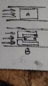
The question is pretty simple. There's a 4" I.D. steel tube with water flowing through at ~12mph. There is a choice between two cylinders. Both diameters are 3.8"; both appear similar externally except the top/bottom of #2. One is solid. The other has a 0.5" inlet on top which leads to another cylindrical solid. The outlet has more cross sectional area than the inlet.

Will each perform identically or will the latter be more effective? ("Grab more" water)

Ascii art not the easiest on the phone, my thinking got me here mathematically:

Cylinder A X- sectional area = 1.9^2 * pi
Cylinder B's =

(1.9^2 * pi - 0.25^2 * pi) + (1^2 * pi)
i.e. 3.8" top with 0.5" inlet to 2" Cylinder beneath

Have no idea if B is correct... or leaning towards the correct idea. (2nd term effectively multiplied by coefficient < 1 but result > the cross sectional area of inlet)
 
Last edited:
Engineering news on Phys.org
  • #2
We need more information to help you. Without a sketch, I have no clue as to what you are trying to do. So please add a sketch.

nrobidoux said:
Will each perform identically or will the latter be more effective? ("Grab more" water)
What do you mean by "perform" and "more effective"? What is the purpose of the two cylinders? What is the purpose of this assembly?
 
  • #3
jrmichler said:
What do you mean by "perform" and "more effective"? What is the purpose of the two cylinders? What is the purpose of this assembly?
Provide greater surface area to push the tool string downhole. "More effective" means using less water to achieve the same speed. So "perform identically" means the ideas for Cylinder B do nothing.
 

Attachments

  • 20221002_094441.jpg
    20221002_094441.jpg
    23.6 KB · Views: 65
  • #4
Nice use of a paper towel there. So this thing is used as a shuttle. It carries that thing inside to some other location in the system?
 
  • Like
Likes russ_watters
  • #5
erobz said:
Nice use of a paper towel there. So this thing is used as a shuttle. It carries that thing inside to some other location in the system?
It's not a picture of the system but of the idea being explored. The reality is currently this part is made of rubber and can be used to assist the movement of the tool string. That is not its primary purpose... and rubber wears down fast. Also the rubber part is not designed to minimize wear.

Our tool string is essentially a 3.125" Cylinder that's about 60' in length and weighs close to 700 lbs. The part to assist us getting down hole is optional but helpful. Meaning that much weight (wet steel on steel) is pushed about 2 miles horizontally by water traveling at 12-15 mph (laminar flow) in a 4" ID steel tube.

Both my initial design and the rubber part are approximately the same height. If anything 1" is thicker than the rubber part.

There is a 2" "neck" about halfway in the string. Either part would slide over it and be locked in place.

I'm curious if Cylinder B provides more effective surface area to push against than Cylinder A. I have all these ideas to complicate the part, this is one of them.

However if complicating makes it work better (more speed for less water)... 👍
 
  • #6
erobz said:
Nice use of a paper towel there.
Have to work with that is available. :)

The question is depicted in the new attachment below. What is more representative of reality for the posing area for Cylinder B?
 

Attachments

  • 20221002_122016.jpg
    20221002_122016.jpg
    42.1 KB · Views: 66
  • 20221002_122030.jpg
    20221002_122030.jpg
    77.5 KB · Views: 69
  • #7
You are slipping a "cup" over the cylinder to make it closer to the pipe diameter so the flow can apply more force?

You are talking about rubber cup or metal cup. You are saying its metal on metal friction, lubricated by water...where is that coming from?
 
Last edited:
  • #8
erobz said:
You are slipping a "cup" over the cylinder to make it closer to the pipe diameter so the flow can apply more force?
Essentially.

Just take what's on the bench in the above picture of the work area and add on similar diameter items until 60' is reached.

In the other picture above... what is most true for B? Where pink is the pushing area. That's really what I'm trying to figure out.

"Because it's fluids" my brain leaned initially towards the left B. After drawing it my brain is at 50/50 only because it's holding out hope for the left side.

Even if I made the hole conical with the wide end at the "internal" cylinder the fluid must slow down as it enters a wider space... slower = less force. So ultimately is B equivalent to A? ( A = Right B)
 
  • #9
With the scenario B on the left there is also pressure acting on the opposite interior wall of the cup that you have not highlighted. If that extra area of the cylinder face is where you think any advantage could lie, there isn't.

1664748373569.png


Furthermore,( for the same reason as above) you must consider the pressure acting on the front of cylinder. It is acting to counter the force that is pushing the cylinder. Flow must bypass to lubricate cylinder on its journey. At the front end the cylinder pressure form that fluid is pushing back. The pressure is lower, but it is the net force on an object which is important, so it needs to be considered.

1664748295310.png


$$ \sum F = F_1 - F_2 - F_{fr} = M a$$
 
Last edited:
  • Like
Likes Lnewqban
  • #10
I was aware of friction... but not of force 2. Thank you.
 

1. How does the diameter of the pipe affect the flow rate of water into the cylinders?

The diameter of the pipe has a direct impact on the flow rate of water into the cylinders. A larger diameter pipe will allow for more water to flow through, resulting in a higher flow rate. On the other hand, a smaller diameter pipe will restrict the flow of water and result in a lower flow rate.

2. What factors influence the pressure of the water as it flows into the cylinders?

The pressure of the water as it flows into the cylinders is influenced by several factors. These include the height of the water source, the diameter of the pipe, the length of the pipe, and the viscosity of the water. Additionally, any obstructions or changes in the pipe's direction can also affect the water pressure.

3. How does the velocity of the water change as it flows from the pipe into the cylinders?

The velocity of the water will decrease as it flows from the pipe into the cylinders. This is because the cross-sectional area of the pipe is larger than that of the cylinders, causing the water to spread out and slow down. However, the velocity may increase again if the cylinders have a smaller diameter than the pipe.

4. What is the relationship between the height of the water source and the flow rate into the cylinders?

The height of the water source has a significant impact on the flow rate into the cylinders. The higher the water source, the greater the potential energy of the water, resulting in a higher flow rate. This is because the water has more force pushing it through the pipe and into the cylinders.

5. How can the flow rate into the cylinders be increased?

There are a few ways to increase the flow rate into the cylinders. One way is to increase the diameter of the pipe to allow for more water to flow through. Another way is to increase the height of the water source to increase the potential energy of the water. Additionally, reducing obstructions and maintaining a smooth, straight pipe can also help increase the flow rate.

Similar threads

  • Mechanical Engineering
Replies
31
Views
2K
  • Mechanical Engineering
Replies
9
Views
2K
  • Mechanical Engineering
Replies
20
Views
7K
Replies
29
Views
5K
  • Mechanical Engineering
Replies
6
Views
11K
  • Introductory Physics Homework Help
Replies
1
Views
937
  • Introductory Physics Homework Help
Replies
19
Views
1K
  • Mechanical Engineering
Replies
1
Views
2K
  • Mechanical Engineering
Replies
2
Views
2K
  • Classical Physics
2
Replies
35
Views
2K
Back
Top