Force diagram of two rods hinged together

In summary, the conversation discusses the correct option for determining the direction of reaction forces in a system involving normal and frictional forces. The experts explain that option (B) is incorrect and option (C) is also wrong due to the larger torque produced by the weight of the right rod. The conclusion is that option (D) is the correct answer as it balances the net torque from the weight compared to option (A). The experts also clarify the direction of forces acting at point P, which involves a hinge and can be determined by considering moments around the point where the rod rests on the ground.
  • #1
songoku
2,294
325
Homework Statement
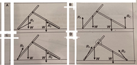
Two identical uniform rods each of weight W are hinged together to form a structure which is resting on rough floor as shown (please see below). If the reaction forces acting on the structure by the floor are ##R_1## and ##R_2##, which of the following shows the forces acting on the structure?
Relevant Equations
Resultant torque = 0

Resultant force = 0
Picture from the question
1632209544366.png


Options:
1632214878148.png


Option (B) is wrong because the both reaction forces have to be slanted since they are resultant of normal force and frictional force.

I think option (C) is wrong because taking the point where the two rods meet as point P and comparing the torque produced by both weights, the torque by the weight of right rod will be larger since the perpendicular distance is larger so there will be clockwise net torque due to bot weights only. Torque produced by both R1 and R2 are also clockwise to the net torque of the system can't be zero.

My guess would be (D) because it seems like R2 will produce bigger counter clockwise torque to balance the net torque from the weight compared to R1 in option (A)

Is there a certain way to determine the correct answer?

I also want to ask about the direction of force acting at point P
1632213957005.png

There will be contact force directed bottom right and friction force directed top right. Is this correct?

Thanks
 

Attachments

  • 1632209567103.png
    1632209567103.png
    38.6 KB · Views: 86
Last edited:
  • Like
Likes Delta2
Physics news on Phys.org
  • #2
songoku said:
Is there a certain way to determine the correct answer?
Yes.
It's a hinge, so consider the torque balance about P for each rod separately.
 
  • Like
Likes songoku
  • #3
haruspex said:
Yes.
It's a hinge, so consider the torque balance about P for each rod separately.
Ah I see, so the correct answer is certainly (D)

I just edit my post to show all the attachments in post#1. Is my diagram correct for forces acting on point P?

Thanks
 
  • #4
songoku said:
I just edit my post to show all the attachments in post#1. Is my diagram correct for forces acting on point P?
Again, it's a hinge. The reaction force can be in any direction, but it does not involve friction.
To see the direction of that reaction, consider moments about the point where the rod rests on the ground.
 
  • Like
Likes songoku
  • #5
Thank you very much haruspex
 

1. What is a force diagram of two rods hinged together?

A force diagram of two rods hinged together is a visual representation of the forces acting on a system of two rods connected by a hinge. It shows the magnitude and direction of each force, as well as the point of application for each force.

2. How do you construct a force diagram of two rods hinged together?

To construct a force diagram of two rods hinged together, you must first identify all the external forces acting on the system, such as weight, tension, or friction. Then, draw each force as a vector with its tail at the point of application and its direction and magnitude according to the given information. Finally, label each force and indicate the point of application and direction of the hinge.

3. What is the purpose of a force diagram of two rods hinged together?

The purpose of a force diagram of two rods hinged together is to analyze the forces acting on a system and determine the net force and its direction. This information can be used to calculate the acceleration and motion of the system.

4. How do you determine the net force on a system from a force diagram of two rods hinged together?

To determine the net force on a system from a force diagram of two rods hinged together, you must first add all the forces acting on the system in the horizontal and vertical directions separately. Then, use the Pythagorean theorem to find the magnitude of the net force and use trigonometric functions to find its direction.

5. How does the angle of the hinge affect the force diagram of two rods hinged together?

The angle of the hinge affects the force diagram of two rods hinged together by changing the direction and magnitude of the forces acting on the system. If the angle of the hinge changes, the forces acting on the rods will also change, which will in turn affect the net force and motion of the system.

Similar threads

Replies
6
Views
794
  • Introductory Physics Homework Help
Replies
30
Views
2K
  • Introductory Physics Homework Help
Replies
6
Views
107
  • Introductory Physics Homework Help
Replies
7
Views
321
  • Introductory Physics Homework Help
Replies
5
Views
886
  • Introductory Physics Homework Help
Replies
5
Views
500
  • Introductory Physics Homework Help
Replies
5
Views
904
  • Introductory Physics Homework Help
Replies
14
Views
2K
  • Introductory Physics Homework Help
2
Replies
42
Views
2K
  • Introductory Physics Homework Help
Replies
8
Views
1K
Back
Top