- #1
paulimerci
- 287
- 47
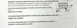
- Homework Statement
- Attached below.
- Relevant Equations
- T = F.d
This is how I interpreted the problem,
a) The net torque about point A is zero. This is because the forces F1 and F2 are equal and opposite, and they act at the same distance from point A. Therefore, they produce torques that cancel each other out..
The force F3 doesn’t does not produce any torque because it acts along the line of action of F1 and F2 and it passes through the COM.
b) The net torque about point B is counterclockwise because the forces F1 and F2 produce torques that are both CCW, while the force F3 doesn’t produce a torque.
c) The net torque at point c is zero, because it's moment is zero.
I'm not sure with the answers I gave, please point out what mistakes I did. Thank you!