Heating of a conductor (1000 turn coil)

In summary, the coil will become very hot, potentially causing the insulation to fail. The coil is not meant for continuous use at 3 amps.
  • #1
StudentDriver
2
0
TL;DR Summary
Suppose I have a current carrying wire that is 20 AWG copper. There is insulation on the copper wire that is rated for 200 degrees C. I have 500 meters of the wire wound into a coil. The coil takes up a total volume of 0.0001157 meters cubed (roughly 1000 turns). Suppose I run 3 amps of current through the coil. Suppose the ambient environment is 25 degrees C. How hot will the conductor become?
Suppose I have a current carrying wire that is 20 AWG copper. There is insulation on the copper wire that is rated for 200 degrees C. I have 500 meters of the wire wound into a coil. The coil takes up a total volume of 0.0001157 meters cubed (roughly 1000 turns). Suppose I run 3 amps of current through the coil. Suppose the ambient environment is 25 degrees C. How hot will the conductor become? Will the wire be able to handle this much current? Will the insulation hold up?
 
Engineering news on Phys.org
  • #2
Welcome to PF.

The temperature will be decided by the rate of heat production, and the thermal resistance of the coil arrangement, losing heat to the environment.

Look up the wire table for resistance of 20 AWG copper wire.
https://en.wikipedia.org/wiki/American_wire_gauge
0.03331 ohm/metre.
500 metres * 0.03331 = 16.655 ohms.
Power W = I2R = 3 * 3 * 16.655 = 150 watt.

How is the coil constructed?
How is the coil cooled?
 
  • Like
Likes jim mcnamara, Rive and russ_watters
  • #3
Imagine a spool of 20AWG copper wire. The inner diameter of the spool is 4 inches. The outer diameter of the coiled wire is 5 inches. The coil is only an inch tall, so it is a short spool, but it is packed pretty densely with windings. There is no cooling system as of yet. I just want to know if this amount of power will cause excessive heating given the constraints. I would like to know what the temperature of the coil will reach if it has been running for a considerable amount of time, say a couple of hours. Would it get hotter and hotter? ***Or would it reach some maximum temperature? What is that max temperature? I think this is the main question that I would like to answer.***

Are there any equations that can be used to figure this?
 
  • #4
StudentDriver said:
I would like to know what the temperature of the coil will reach if it has been running for a considerable amount of time, say a couple of hours.
You can get a ballpark idea from the power calculation of 150W by @Baluncore and imagine a 150W incandescent lightbulb in a small box about the size of your coil. How hot do you think that will get? Too hot to touch, that's for sure. Too hot to cause the insulation to fail? With the 200C rating, I doubt it, but this coil will be quite hot.

What is the application?
 
  • Like
Likes Windadct and DaveE
  • #5
StudentDriver said:
I would like to know what the temperature of the coil will reach if it has been running for a considerable amount of time, say a couple of hours. Would it get hotter and hotter? ***Or would it reach some maximum temperature? What is that max temperature? I think this is the main question that I would like to answer.***

Are there any equations that can be used to figure this?
This is a heat transfer problem. You have a volume of material generating a known amount of heat. That heat is (presumably) transferred from the surface of the coil to room air. The heat transfer area (surface area of the coil) is known. Therefore, you need to transfer a known amount of heat through a known area to a known ambient temperature.

The heat transfer coefficient (search the term) is the relation between heat flow per unit area and temperature difference between the coil surface and the ambient air. There are published numbers for heat transfer coefficients; those numbers span such a wide that that they are almost always useless. There are published equations to estimate heat transfer coefficients. Those can be found in any basic book on heat transfer. The Wikipedia article has some also. The topic is too large for an internet post, so you will need to do your own reading studying.

After you estimate the surface temperature of the coil, the next step is to estimate the maximum temperature inside the coil. That temperature is a function of the rate of heat generation, the geometry of the coil, and the thermal conductivity (search the term) of the coil. The thermal conductivity of a coil may be hard to find because it depends on the wire insulation, how it is wound, and any potting.

Or you could just build a coil, put a known voltage and current through it, and measure the temperature. That would be much easier, faster, and would give more accurate results.
 
  • Like
Likes russ_watters and DaveE
  • #6
jrmichler said:
Or you could just build a coil, put a known voltage and current through it, and measure the temperature. That would be much easier, faster, and would give more accurate results.
Just don't use your finger as a temperature probe. Don't ask me how I know this... o0)
 
  • Like
  • Haha
Likes sophiecentaur and DaveE
  • #7
berkeman said:
Just don't use your finger as a temperature probe. Don't ask me how I know this... o0)
And yet we still do it from time to time, LOL. In addition to the burn there's the humiliation of knowing you just did something stupid that you'd done before.
 
  • Like
Likes sophiecentaur and berkeman
  • #8
With a little approximation
if we shall consider the spool in a steel box of 5" diameter and 1" height, then, according to
“How to calculate the temperature rise in a sealed enclosure”
we may calculate first the outer wall temperature and then the maximum wire temperature.
At first, consider the steel wall temperature Tes =124oC [calculated by iteration before!:smile:
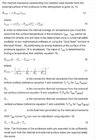
] and the total resistance will be:
R124oC
23.35286​
ohm
Plosses=
210.1757​
W [3^2*R]
See attached the results.
As it is clear, only convection and radiation were considered.
From the turns of column at 4" diameter up to 5" diameter
the heat passes by conduction. Now, we consider all losses are evacuated horizontally-no top and no bottom evacuation[ for this inner part, only], so, we may compare this with a cable single core insulation temperature drop.
According to IEC 60287-2-1 insulation thermal resistance is
T1=λ/2/pi()*ln(di/dc) per unit length.
According to J. Stolpe we may consider the entire cable as insulation only and λ=4 K.m/W.
T1=4/2/pi()*ln(5/4)*25.4/1000 =0.003608 K/W-conduction from inner column to outer column temperature drop will be then:
T1*Plosses=0.758oC [negligible ].
Then the maximum conductor temperature is 124+0.76=125oC
 

Attachments

  • sealed bobbin temperature calculation. results.jpg
    sealed bobbin temperature calculation. results.jpg
    36.5 KB · Views: 50
  • #9
Some of other attachments are still out
 

Attachments

  • sealed bobbin temperature calculation aux.jpg
    sealed bobbin temperature calculation aux.jpg
    45.4 KB · Views: 50
  • #10
Bad news is that since IEC 60287-2-1 does not consider a cable length different than the unit I thought I have to multiply by actual length. Now, considering the general conduction law:
Q/A=λ*dT/dx and A=2*PI()*radius*length, I have to divide by length.
Good news: if the insulation material is Tefzel [for 200oC] then as per DuPont- the manufacturer- λ=0.24 W/m/oK.
Finally, T1=T1=0.24/2/pi()*ln(5/4)/25.4*1000=0.33557
Plosses is now 266.4 W
DT=0.33557*266.4=89.4 and Tc=220 oC!!!!!
 
  • #11
Then, now, Tes=130.5 oC of course.
 
  • #12
Looks like I was wrong again. In the formula from IEC 60287-2-1, the notion of thermal resistance is used, and in DuPont's article it refers to thermal conductivity, which unfortunately means thermal resistance is 4.
 
  • #13
So, convection and radiation are negligible before the wire temperature will be more than 1000 oC.
If Plosses=I^2*Ro*(1+kT*(T-To)) where Ro it is the wire resistance at To=20oC and kT=0.00393 [IEC st. 60228].
The temperature rise [in adiabatic case]of the wire mass for a dtime duration will be dT.Then we consider the same temperature along the entire wire.
The heat REQUIRED in order to increase the temperature with dT will be:
I^2*Ro*(1+kT*(T-To))*dtime
and the wire mass will receive it as capth*weight*dT where
capth=copper heat capacity=0.0921 kcal/kg/oC=0.3853464 kJ/kg/oC ; weight=2.314 kg then:
I^2*Ro*(1+kT*(T-To))*dtime=capth*weight*dT
or
dT/f(T)=dtime*I^2*Ro/(capth*weight) where:
f(T)=(1+kT*(T-To))
(1+kT*(T-To))=(a+b*T) where a=1-kT*To=0.9214 ;b=kT=0.00393
ʃdT/f(T)=1/b*ln[(a+b*T)/(a+b*To)]
ʃdtime*I^2*Ro/(capth*weight)= I^2*Ro/(capth*weight)*(time-time 0)
Then
[(a+b*T)/(a+b*To)]=exp[b*I^2*Ro/(capth*weight)*(time- 0)]
(a+b*T)= {exp[b*I^2*Ro/(capth*weight)* time]-1}-a )*(a+b*To)
T= {(a+b*To)*[exp(b*I^2*Ro/(capth*weight* time)-1]- a}/b
For time= 1.515 sec
b*I^2*Ro/(capth*weight)= 0.657675
T={(0.9214+0.00393*20)*[exp(0.6576*1.515)-1]-0.9214}/0.00393= 200.2 oC
 
Last edited:
  • #14
The logic is correct. But, still I was wrong-I am sorry!. The thermal capacity of the copper it is 0.385 KiloJ/kg/oK and Qlosses= A^2*ohm*second are in J. So the last equation has to the following:
T={(0.9214+0.00393*20)*[exp(0.6576*1.515/1000)-1]-0.9214}/0.00393
For 1515 sec the copper temperature will be 200 oC
 
  • #15
StudentDriver said:
TL;DR Summary: Suppose I have a current carrying wire that is 20 AWG copper. There is insulation on the copper wire that is rated for 200 degrees C. I have 500 meters of the wire wound into a coil. The coil takes up a total volume of 0.0001157 meters cubed (roughly 1000 turns). Suppose I run 3 amps of current through the coil. Suppose the ambient environment is 25 degrees C. How hot will the conductor become?

How hot will the conductor become? Will the wire be able to handle this much current? Will the insulation hold up?
From what you have found out and from the responses, I guess it's pretty clear to you why people, in real life, don't use copper wire for heating elements. You can do a much better design with 150W output, using resistance wire (Nichrome is a popular example.) Using a similar volume of heater, you can get the required resistance with a much shorter length of wire with space around all the (much fewer) turns with room inside for air to circulate and avoid hotspots. Think of a basic toaster element and the way it's constructed and bear in mind that toasters are actually more powerful (say 1kW) and they take care of themselves thermally. Also, a 200W oil filled heater uses a nichrome coil and stays at a sensible temperature with no fire risk.

This is what Engineering is all about; choices and Copper is not a good choice.
 
  • #16
sophiecentaur said:
This is what Engineering is all about; choices and Copper is not a good choice.
Unless you want to make an electromagnet.
 
  • Like
Likes sophiecentaur
  • #17
Baluncore said:
Unless you want to make an electromagnet.
Very true. However, if you need to dissipate that much power then perhaps the basic constraints should be re-examined. A bigger volume with circulating coolant is the way power transformers handle the heat. The magnetic circuit is part of the overall equation and design. The Bitter Magnet is a high end solution and that design involves the right choice of coil layout and cooling. A lot of trouble to DIY, though.
 
  • Like
Likes Babadag
  • #18
StudentDriver said:
Suppose I have a current carrying wire that is 20 AWG copper.
There is insulation on the copper wire that is rated for 200 degrees C.
I have 500 meters of the wire wound into a coil.
The coil takes up a total volume of 0.0001157 meters cubed (roughly 1000 turns).
Suppose I run 3 amps of current through the coil.
Suppose the ambient environment is 25 degrees C.
How hot will the conductor become?
According to Radix catalogue, the overall diameter of the wire it is 1.5 mm [0.059"] then the wire volume =500*1.5^2/4/1000^2=0.000281 m^3
However, since the wire cross section area is circular-not square-
there are some other corrections to do.
If the cross-section area height is 10.5"[not 1" as supposed to be]
and the interval between 5" and 4" is 0.5"[both sides], then the number horizontal cables is 0.5/0.059=8 and the vertical column of 10.5" presents 10.5/.059= 178 cables. Let's take 175.
Total number =8*175=1400
If the average length of one turn it is pi()*4.5"=14.14" [0.359 m] the total length =1400*0.359=502.6 m
By the way, I found another mismatch: one in my last formula.
exp[b*I^2*Ro/(capth*weight)*(time- 0)] ǂexp[b*I^2*Ro/(capth*weight)* time-1], since “time” and “0” are not an integral limit, but a single variable.
So, I have to delete -1 and the result is as follows:
T={(0.9214+0.00393*20)*[exp(0.6576*815/1000)]-0.9214}/0.00393= 200.42 oC
815 seconds it is close to an average [approximate] calculation 768.45 [94.3%.]
As I said above : it is impossible to press 500 m of this wire in a volume limited by the dimension proposed in the open post.
I agree with 5" outside line ,4" the inside line but 1" height it is impossible. We need at least 10.5" height [see the attached sketch]
Now, if the total time to reach 200oC, in adiabatic mode , it is more than 10 seconds the cooling may be significant -through convection and radiation.
Radix 20 awg copper 500 m length bobbin.jpg

An approximate calculation shows in approximate 3000 seconds the heating will be stabilized on 230oC. I apologize. Since I am very busy now, a more accurate calculation I cannot do for the time being
 
  • Like
Likes sophiecentaur
  • #19
That's for plastic insulated wire. Coils are normally wound with magnet wire. Magnet wire insulation is about 0.001" thick, so 20 gauge wire would be 0.033" diameter. Random link to a table of magnet wire dimensions: https://www.coonerwire.com/magnet-wire/.

A quick calculation for a coil 4" ID and 5" OD finds overall length slightly over 3". With 1/3 the surface area of the above calculation, the surface will get even hotter.

Has the effect of temperature on wire resistance been included in the above calculations? Resistance increases with temperature, current stays constant, so voltage and total heat increases. This is also a way to measure the average temperature of the wire just by measuring the voltage as the coil heats up.
 
  • Like
Likes DaveE and berkeman
  • #20
A more accurate calculation resulted 120oC [if the current is always 3 A] in 475 seconds. Another method using iteration for all 50 sec get a result of 113oC in 450 sec.
 

1. What is the purpose of heating a conductor?

The purpose of heating a conductor is to increase its temperature, which can cause changes in its physical properties such as resistance, conductivity, and magnetic properties.

2. How does heating affect the resistance of a conductor?

Heating a conductor can increase its resistance due to the increased vibration of its atoms, which hinders the flow of electrons and causes more collisions.

3. Can heating a conductor lead to overheating and damage?

Yes, excessive heating can lead to overheating and damage to the conductor, especially if it is not designed to withstand high temperatures.

4. What is the relationship between the number of turns in a coil and its heating?

The number of turns in a coil can affect its heating as it determines the amount of current flowing through the coil and the strength of the magnetic field, which can generate heat through resistance.

5. What are some factors that can influence the heating of a conductor?

Some factors that can influence the heating of a conductor include the material of the conductor, the current passing through it, the duration of heating, and the environment in which it is placed.

Similar threads

Replies
7
Views
2K
Replies
16
Views
10K
  • Electrical Engineering
3
Replies
72
Views
15K
  • Electrical Engineering
Replies
31
Views
8K
  • Introductory Physics Homework Help
Replies
2
Views
745
  • Electrical Engineering
Replies
14
Views
2K
Replies
28
Views
41K
Replies
1
Views
1K
  • Electromagnetism
2
Replies
43
Views
1K
  • Electrical Engineering
Replies
16
Views
2K
Back
Top