- #1
Purpleshinyrock
- 27
- 6
- TL;DR Summary
- Hello I need help understanding this lab class (my first one) about assembling a circuit using 3 resistances, an 2 multimeter and a power supply on a breadboard(protoboard)
Hello. I am trying to replicate my first lab class and I was having troule the whole time , the teacher has to attend to other students i ended up not understanding fully what i needed to do.
questions I have: what wires connect on the v(multimeter )and (A )multimeter with the resistance .Heres the circuit as well as the goals of the class down bellow.

1. Assemble the circuit in figure a) with a voltmeter, ammeter and with R = 2.7KΩ. apply
voltages: 5V; 10V; 15V; 20V; 25V, varying the voltage at the source, noting the voltages indicated on the voltmeter and the respective current intensities indicated on the
ammeter
2. Change the value of R to 10MΩ. With a voltage of 25V, note the intensity of
current indicated on the ammeter and the corresponding voltage indicated on the voltmeter.
3. With R = 10MΩ, assemble the circuit in the configuration in figure b). with the same tension
25V, note the current intensity indicated on the ammeter and the voltage indicated
on the voltmeter.
1. For item 1, graph using EXCEL, Matlab or program
equivalent voltages as a function of currents (in abscissa).
2. From the results of paragraph 1, it can be concluded that there is direct proportionality between the
voltage and current? Justify. See what the slope of the line corresponds to, what is the
value?
heres what i did so far:
*find a simulator so I can practice without damaging my breadboard(or blowing up the house)
*learn how to display the resistors in series and paralel
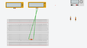
 here's an image o what I am trying to do or exercise 1.
items in the image
yellow ones
2 multimeters : the one on the let set or volts (V), the one on the right set for amperes(A)
3 resistors : the one in the bbreadbord is suposed to be 2,70 (it registered as 2 because i didnt enter as a ".")
grey item(power supply).
Can you help me understand so that I may be better prepared next time?
Your time and attention are deeply appreciated.
Thank you.
questions I have: what wires connect on the v(multimeter )and (A )multimeter with the resistance .Heres the circuit as well as the goals of the class down bellow.
1. Assemble the circuit in figure a) with a voltmeter, ammeter and with R = 2.7KΩ. apply
voltages: 5V; 10V; 15V; 20V; 25V, varying the voltage at the source, noting the voltages indicated on the voltmeter and the respective current intensities indicated on the
ammeter
2. Change the value of R to 10MΩ. With a voltage of 25V, note the intensity of
current indicated on the ammeter and the corresponding voltage indicated on the voltmeter.
3. With R = 10MΩ, assemble the circuit in the configuration in figure b). with the same tension
25V, note the current intensity indicated on the ammeter and the voltage indicated
on the voltmeter.
1. For item 1, graph using EXCEL, Matlab or program
equivalent voltages as a function of currents (in abscissa).
2. From the results of paragraph 1, it can be concluded that there is direct proportionality between the
voltage and current? Justify. See what the slope of the line corresponds to, what is the
value?
heres what i did so far:
*find a simulator so I can practice without damaging my breadboard(or blowing up the house)
*learn how to display the resistors in series and paralel
items in the image
yellow ones
2 multimeters : the one on the let set or volts (V), the one on the right set for amperes(A)
3 resistors : the one in the bbreadbord is suposed to be 2,70 (it registered as 2 because i didnt enter as a ".")
grey item(power supply).
Can you help me understand so that I may be better prepared next time?
Your time and attention are deeply appreciated.
Thank you.
Attachments
Last edited: