Help with Torque and Motor size gearbox requirements

In summary, the user is working on a machine that requires a motor to move a weight. They need help sizing the motor. They have four gears, with different sizes, and they need to find the force required to move each gear and the acceleration and deceleration times. They also need to calculate the friction force and the peak acceleration force.
  • #1
Amayer14
10
0
TL;DR Summary
Help with Torque and Motor size gearbox requirements
Hello,

New here but thanks in advance for help.

I need help sizing a motor/gearbox for a machine i am working on. known specs are below:
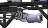
I have a solid shaft driving 4 gears that are all different sizes, the gear with the most weight attached has a pitch diameter of 7.65 in and they are sized evenly so the 4th gear has a ratio of 1:4 from the larger gear. Gears are pressed and have set screws onto the shaft and may potentially get a key way as well.

Its task is to move a weight of 66 pounds horizontally on a linear bearing rail. I don't know friction numbers for this bearing but they are low friction grease-less linear ball bearings. The other 3 gears are pulling/pushing 36 pounds each horizontally on a linear bearing rail. So one gear moves 66 lbs and the other three move 36 lbs each.

They basically move a set of support rails evenly at different distances but run off the same shaft.
shaft coupled to the motor is 1" in diameter and roughly 14" long.
I need to move this weight 160 inches in 4 seconds.
i would like a safety factor of 3 as well.

there are no concentration factors on the shaft as of right now.
for any other information, ask and i should have access to most measurements.
 
Last edited:
Engineering news on Phys.org
  • #2
We need more information.

It is unclear what you are trying to do. We need a sketch. The sketch should show the number of teeth on each gear.
Are you pushing with forces of (36) (66) pounds, or are you moving masses of (36) (66) pounds?
If you are moving masses, you need to find the force. The linear bearing manufacturer has this information in their catalog.
Are driving it with an induction motor, where the motor starts, runs at constant speed, then stops?
Or are you driving it with a servomotor, where you can program the motion profile?
If a servomotor, will you program a short acceleration, constant velocity, then a deceleration? Or constant acceleration halfway, then constant deceleration to a stop?

Put together this information, then we can help you through the next step.
 
  • #3
I will attempt to get a couple screen shots of the design. I am moving masses of 66lbs and 36lbs. the larger of the 4 gears is moving a mass of 66lbs. The other gears are moving a mass of 36lbs each. so a total of 174lbs (Roughly) is being moved at once. the HIWIN linear bearing has a coefficient of friction near .004 according to the catalog and mass is moving horizontally.

The motor will start, move the masses into there position and stop controlled via transducer. Then start when prompted to move the mass back to the start position and so on. The motor options are open as that's what I'm trying to determine what will be the best fit for me.

Information on the Chain drive gears are as follows.

Gear 1: Mcmaster-Carr #6236k215
Gear 2: Mcmaster-Carr #6236k187
Gear 3: Mcmaster-Carr #6280k853
Gear 4: Mcmaster-Carr #6280k664

I have not factored in weight of chain into my mass.
 

Attachments

  • Capture 3.PNG
    Capture 3.PNG
    35.2 KB · Views: 100
  • #4
I know i have a motor drawn in the model but its for visual aid only at this point.
 
  • #5
You need to calculate the force to:
1) Move each mass,
and
2) Accelerate each mass.

You are apparently describing a geared induction motor that starts and stops on command. Good starting assumptions for this type of drive are 0.5 second to accelerate, 1.0 second to decelerate, and the rest of the move at constant velocity. You need to calculate the constant velocity under those assumptions.

Hint: Make a sketch of acceleration vs time, then calculate a similar sketch of velocity vs time from the acceleration sketch.

Your screen shot appears to show that the masses are driven through chain attachments by two different sprockets of different diameters. If so, one mass is moving a different distance than the other mass. Do the above calculation for the mass that moves the farthest, the velocity and acceleration of the other mass is proportional to the drive ratio.

Calculate friction force and peak acceleration force for each mass. From that, and the drive sprocket diameters, calculate torque on the drive shaft. Calculate peak RPM of the drive shaft. Most induction motors run at 1800 or 1500 RPM depending on your electrical power. Now you can calculate drive ratio and motor power.

I will be back on Tuesday, so take your time and do it carefully. Then recheck your work.
 
  • #6
Ok,

So i calculated that for the first gear and mass, peak acceleration force is 60N and friction force is .0275lbf?

I'm not sure that this is even correct, and was hoping to use this as a learning experience for me.

The first 66 lb weight moves 160 inches in 4 seconds with .5 seconds to get to constant velocity and then assuming constant velocity for 2.5 seconds before deceleration.

The rest is proportional and can be added when to that point. I'm not sure how to get the other answers you are looking for (Peak RPM and torque) otherwise i probably wouldn't be here.

Any further help is appreciated.
 
  • #7
Torque value of 211.5 lbf?
 
  • #8
Are you 'moving' or explicitly lifting? (This is where a diagram could save a lot of time, second guessing the situation.)
 
  • #9
Wrong. Show your velocity vs time plot for the longest move. A hand sketch is sufficient, but you must label times and velocity. You will do this before I reply again.
 
  • #10
I will figure it out on my own, thanks for your time.
 
  • #11
Amayer14 said:
I will figure it out on my own, thanks for your time.
This is unfortunate. You are throwing your toys out of the pram when all that has been asked of you is to talk in the right language and provide the proper information.
You will not figure it out unless you use the right approach. Pay a consultant and they will require the same information that PF has.
 
  • Like
Likes BvU
  • #12
The mechanism will be dangerous if it is too powerful, or too fast.
There will need to be travel limit switches at the entry to safe stopping zones.
There will need to be a safe emergency stop system.
1. What is the maximum permitted velocity of any sliding component ?
2. What is the maximum time or distance permitted to stop completely ?
Those are the critical parameters that will determine motor power and gearbox ratio.
Check your insurance.
 
  • Like
Likes sophiecentaur
  • #13
sophiecentaur - I have provided all information asked to this point so I'm not sure what has you complaining, if you require more information - ask.

Baluncore - Machine is hard guarded and both ends of the bearing rails have cushions and runaway stops, e-stop circuit has been accounted for and is 60204 compliant. chain moves my components and is rated for much more than my application.

My problem - I do not normally work with gears and motors so it is fairly foreign to me because most of my designs are pneumatically driven, which is why i came here to this forum to ask for help but so far iv'e only been made a fool for no reason getting asked to make calculations that i specifically came here for help with because i don't remember/know how to do them. If you require more information to help me, i will provide. But i do not have time to sit around wasting my time getting asked to do calculations that i don't know how to do as this is the reason i came here.

Check yourself. Doesn't take much more effort to be kind than it does to be a jerk
 
  • #14
@Amayer14 sorry to make you cross but unfortunately we get many questions from people who are without a clue. We err on the safe side and that should be reassuring for you. If you are used to hydraulic systems then all the factors would be familiar.
We don't know what you know and what you don't know if it's not all written down. So we ask dumb questions some times.

From the numbers you ave quoted, this proposed system could be risky if it's not engineered properly - that's why you are getting awkward questions.
 
  • #15
I can understand that, sorry for getting frustrated. But it would be similar to me asking you if you know the ins and outs of shingling a house. Nobody knows everything, but everyone knows something. If you have questions for me, I'm more than happy to try my best to answer them. But don't tell me to do something that i don't know how to do just to say "wrong" and then provide no further help. I have done some hydraulic mechanisms and done some fluid flow and pressure calculations but mostly for my current career it is all pneumatic systems, but its been since college that iv'e done gearing and torque calculations and obviously did not retain well.
 
  • #16
I think we can ignore slide friction.
I am concerned that the gearbox shown in the image might be a worm drive. That might need a slip-clutch, flexible link, or belt at the output, so a sudden stop of the motor or slide does not damage the gearbox.

Since all slides on rails are driven at different speeds, totals for the different rates are separate. To begin I would gather and tabulate the data for each separate slide.
1. No of teeth on the drive sprocket.
2. Pitch of that chain, or pitch diameter of that sprocket.
3. Maximum weight of that chain. (Chains are all different lengths).
4. Maximum weight of that moving slide.

Are you able to construct that 4x4 table once to save others searching through posts and duplicating the effort and questions ?
 
  • #17
Baluncore, sorry for the delay in my response. Its been hectic here.

If i understand you correctly this is the information you are requesting...

Gear one:
48 tooth sprocket
24.017 inches per rev of sprocket
Pitch diameter of 7.56"
The weight moves a total of 160 inches
the weight has a total mass (including chain and slide) of 86 pounds roughly
 
  • #18
That is only one gear and slide.
There are three other gears, moving three other slides.
 
  • #19
I wanted to make sure this is the information needed, and i also thought they would be proportional.
Here is the information on the other three.

Gear Two:
36 tooth sprocket
18.022" inches per rev of sprocket
Pitch diameter of 5.74"
The weight moves a total of 120 inches
the weight has a total mass (including chain and slide) of 48 pounds roughly

Gear 3:
24 tooth sprocket
12.034" inches per rev of sprocket
Pitch diameter of 3.83"
The weight moves a total of 80 inches
the weight has a total mass (including chain and slide) of 44 pounds roughly

Gear 4:
12 tooth sprocket
6.07" inches per rev of sprocket
Pitch diameter of 1.93"
The weight moves a total of 40 inches
the weight has a total mass (including chain and slide) of 40 pounds roughly
 
  • #20
If roller chains are all 0.5" link pitch.
Gear, teeth, circum", PD", dist", mass lbs
1, 48, 24.0, 7.64, 160, 86
2, 36, 18.0, 5.73, 120, 48
3, 24, 12.0, 3.82, 80, 44
4, 12, 6.0, 1.91, 40, 40
 
  • Like
Likes Amayer14

What is torque and why is it important in motor size and gearbox requirements?

Torque is a measure of rotational force, or the ability of a motor to rotate an object. In motor size and gearbox requirements, torque is important because it determines the amount of force that can be applied to move a load or overcome resistance. A higher torque is needed for heavier loads or more resistance.

How do I calculate the required torque for my application?

The required torque can be calculated by multiplying the load force by the distance from the center of rotation to the point where the force is applied. This will give you the torque in units of force times distance (e.g. Nm or lb-ft). It is important to also consider any additional factors such as friction or acceleration when calculating the required torque.

What factors should be considered when selecting a motor size and gearbox?

When selecting a motor size and gearbox, factors such as the required torque, speed, and power, as well as the size and weight of the load, must be considered. The type of application and environment, as well as the cost and availability of different motor and gearbox options, should also be taken into account.

What are the consequences of using a motor with insufficient torque for my application?

If a motor with insufficient torque is used for an application, it may not be able to move the load or overcome resistance. This can result in the motor stalling or overheating, leading to potential damage and failure. It is important to ensure that the motor has enough torque to handle the demands of the application.

How can I optimize the torque and motor size for my application?

To optimize the torque and motor size for your application, it is important to carefully consider all the factors involved, such as the load requirements, speed, and power. You may also want to consult with a motor and gearbox expert or use online calculators to determine the most suitable options. Testing and fine-tuning may also be necessary to achieve the optimal torque and motor size for your specific application.

Similar threads

Replies
1
Views
620
  • Mechanical Engineering
Replies
12
Views
2K
Replies
3
Views
2K
  • Mechanical Engineering
Replies
2
Views
2K
  • Mechanical Engineering
Replies
5
Views
3K
  • Mechanical Engineering
Replies
17
Views
3K
Replies
2
Views
1K
  • Mechanical Engineering
Replies
6
Views
2K
  • Mechanical Engineering
Replies
11
Views
2K
  • Mechanical Engineering
Replies
6
Views
2K
Back
Top