How to Calculate Thevenin Equivalent Circuit

In summary: This is different than the ideal active devices you mention, which are not subject to the constraints of the rest of the circuit.
  • #1
LearnerErnie
2
0
Homework Statement
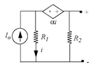
Find the Thevenin equivalent circuit of the attached circuit. Assume that α has units of Ohms.
Relevant Equations
KCL: The sum of currents into and out of a node in a circuit equals 0.
KVL: The sum of voltages in any closed loop is 0.
V = IR
First, I calculate the Thevenin resistance by treating the independent current source I0 as an open circuit and noticing that the resistance of the dependent voltage source is α (since V=IR and the voltage across the dependent voltage source is given by αi.

In this way, I have:

RTH = 1 / (1 / R2 + 1 / (R1 + α)) = (R1 + α)R2 / (R1 + R2 + α)

Now, for the Thevenin voltage VTH, I thought it might be easier to find the short circuit current IN through the output terminals and then simply multiply by RTH to get VTH.

This is where my analysis gets confused.

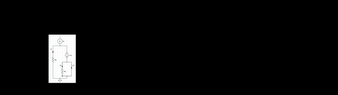
I've attached my redrawn circuit when I short the output terminals. Using this circuit, I think I can say the following using KCL:

I0 = I1 + I1 (since the current through the CCVC is I1)

I1 = I2 + IN (can I ignore I2 since the current will completely avoid the resistor and prefer the shorted path?)

If I can ignore the resistor, then I1 = 0 + IN.

At this point, I get a bit stuck. The equations don't really seem to tell me anything useful, and I don't think that IN = I1, but I don't know where my confusion lies exactly.

If I write out all the branch currents explicitly and solve it in a very granular fashion, I find that ITH = I0, but I do not know how to derive this result in a more "intuitive" manner.

If someone could point me in the right direction, that would be very helpful. Thanks.
 

Attachments

  • latest.png
    latest.png
    9.8 KB · Views: 103
  • latest.png
    latest.png
    1.2 KB · Views: 99
Physics news on Phys.org
  • #2
LearnerErnie said:
...the resistance of the dependent voltage source is α (since V=IR and the voltage across the dependent voltage source is given by αi.
α is just a scale factor for determining the voltage of the CCVS. It happens to have units of ohms, but it is not the internal resistance of the CCVS. A dependent source is like an independent source--it has no internal resistance.
 
  • Like
Likes DaveE
  • #3
lewando said:
α is just a scale factor for determining the voltage of the CCVS. It happens to have units of ohms, but it is not the internal resistance of the CCVS. A dependent source is like an independent source--it has no internal resistance.

Ah got it! Thanks very much! So we've effectively shorted the entire circuit, since the current will take the path of least resistance, meaning ##I_N = I_0##? I think this means the current through the CCVC must be ##I_0##? If so, that's super intuitive and makes perfect sense. If not...I guess I'm even more confused 😅...

That also means that ##R_{TH}## was calculated incorrectly. So we have

$$R_{TH} = \frac{R_1R_2}{R_1 + R_2} \quad\text{and}\quad I_N = I_0$$

Thus, $$V_{TH} = \frac{I_0R_1R_2}{R_1 + R_2}$$

I still feel like I'm missing something, since I haven't used the CCVC at all.
 
Last edited:
  • #4
LearnerErnie said:
I still feel like I'm missing something
Does it make sense to you that α doesn't appear anywhere in your solution? What if Io, R1, and R2 were all set to 1 and α varied from 0 → ∞. Would you expect the circuit to behave differently?

One way to find the Thevenin equivalent is to use the calculations for the open circuit voltage and the short circuit current. Try again with that approach.
 
  • #5
I could have been clearer, so my apologies. I did not mean zero resistance. I should have said these are ideal active devices and cannot be modeled a resistor. It is true that for a given DC operating point there will be a voltage across and current through a dependent source leading you to think about a resistance. But under different load conditions, or different circuit component values, the dependent source will try to maintain its constant voltage (or current) and yet allow the corresponding current (or voltage) to change as needed.
 
  • #6
Yes.
A voltage source (dependent, or not) WILL have the defined voltage across it with whatever current through it that the circuit generates as a consequence of its, and other, voltages. Voltage sources have, by definition, 0Ω of series resistance, since the voltage will not change as a function of the current through it. Current sources are similar; their current is defined and it won't change if the voltage across it changes. They have infinite series resistance (or 0 shunt resistance for the Norton equivalent). Their voltage is entirely dependent on how the rest of the circuit responds to the current that MUST be flowing through the current source.
 

What is Thevenin Equivalent?

Thevenin Equivalent is a simplified representation of a complex electrical circuit that consists of a voltage source and a series resistance. It is used to analyze and understand the behavior of a circuit, especially in terms of voltage and current.

Why is Thevenin Equivalent important?

Thevenin Equivalent is important because it allows us to replace a complex circuit with a simpler equivalent circuit, making it easier to analyze and understand. It also helps in predicting the behavior of the circuit under different conditions and in designing more efficient and reliable circuits.

How do you find Thevenin Equivalent?

To find Thevenin Equivalent, you need to follow these steps:1. Remove all the load components from the circuit.2. Calculate the open-circuit voltage at the load terminals.3. Calculate the equivalent resistance seen from the load terminals.4. Draw the Thevenin Equivalent circuit with the open-circuit voltage and equivalent resistance.

What are the applications of Thevenin Equivalent?

Thevenin Equivalent is used in various applications such as:1. Circuit analysis and design.2. Troubleshooting and fault detection.3. Simulation and modeling of complex circuits.4. Designing power supplies and amplifiers.5. Network analysis and optimization.

What are the limitations of Thevenin Equivalent?

Thevenin Equivalent has some limitations, such as:1. It is only applicable to linear circuits.2. It assumes that the circuit parameters are constant.3. It does not take into account the effects of temperature and frequency.4. It is not accurate for circuits with non-linear elements.5. It does not consider the effects of noise and other external factors.

Similar threads

  • Engineering and Comp Sci Homework Help
Replies
10
Views
2K
  • Engineering and Comp Sci Homework Help
2
Replies
42
Views
5K
  • Engineering and Comp Sci Homework Help
Replies
7
Views
2K
  • Engineering and Comp Sci Homework Help
Replies
2
Views
921
  • Engineering and Comp Sci Homework Help
Replies
4
Views
2K
  • Engineering and Comp Sci Homework Help
Replies
1
Views
1K
  • Engineering and Comp Sci Homework Help
Replies
12
Views
1K
  • Engineering and Comp Sci Homework Help
Replies
10
Views
2K
  • Engineering and Comp Sci Homework Help
Replies
8
Views
2K
  • Engineering and Comp Sci Homework Help
Replies
9
Views
4K
Back
Top