- #1
IronaSona
- 38
- 7
- Homework Statement
- .
- Relevant Equations
- .
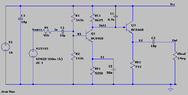
Hi i got a question ,how do i calculate the input resistance ,of the RS resistor ,so i would get half of the voltage of the voltage source (500mA) .I've created the circuit in ltspice and found out that its around 95K ohms to get 250mA,but how would i calculate it .
Ive also attached my calculations which i used to get 1.5vpp
Ive also attached my calculations which i used to get 1.5vpp