- #1
Mary09
- 7
- 0
Hey everyone,
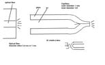
I am trying to couple light from an optical fiber connected to an LED (365nm) into a small glass capillary which is pulled on one end and should be used as a small light source. The idea is to use the glass as a light guide. Has anyone tips for efficient incoupling of the light?
I would really appreciate your help.