Problem on Parallel Plate Waveguide

In summary, the conversation discusses a problem involving a waveguide with two sections of different permittivities and the calculation of the cutoff frequency for the TM mode. The person is unsure if their approach is correct and asks for guidance on finding the angle of incidence and the specific frequency for the TM1 mode. They are also unsure if this problem involves any previously covered topics. The conversation ends with a request for the specific topic that can help solve the problem.
  • #1
warhammer
151
31
Homework Statement
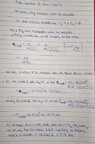
Plate separation is given as 2*10^-3 m. Waveguide propagates through two different permabilities. Find Frequency of Wave (Imgur Link with the Figure of the Problem is attached as well)
Relevant Equations
##f(cutoff) = {m}/{(2d*√μϵ)}##
The Imgur Link of the Problem with the figure - Problem Link. I did not paste it here as the post upload quality seemed heavily pixelated for some reason.

For this problem, what I did was to divide the waveguide into 2 sections of distinct permabilities to calculate the cutoff frequency. Since the problem asks for frequency of wave specifically I calculated the range of frequencies for which the waveguide will propagate in TM Mode.

Now I am confused as to whether this approach is fine or not (I think it should be because we do not have any more data supplied with the problem). Also, is this bifurcation technique fine or should I be finding the average of the 2 cutoff frequencies.

I have attached my work. I sincerely request someone to please take a look and guide me if my method is correct or not..
 

Attachments

  • IMG_20221101_005218.jpg
    IMG_20221101_005218.jpg
    45.8 KB · Views: 49
Physics news on Phys.org
  • #2
From the statement of the problem, what can you say about the value of the reflection coefficient at the boundary between the two dielectrics?

Can you use this value of the reflection coefficient to figure out the angle of incidence of the TM1 waves at the boundary between the two dielectrics?

I believe that the answer to the problem will be a single frequency, not a range of frequencies.

--------------------------------------------------------------------------------------------------------------------
(Your written work seems to imply that the cutoff frequency for a particular mode is the highest frequency that can propagate for that mode. But the cutoff frequency is the lowest frequency that can propagate. I don't think you will need the cutoff frequency.)
 
  • Like
Likes warhammer
  • #3
Thank you so much for your response!
TSny said:
From the statement of the problem, what can you say about the value of the reflection coefficient at the boundary between the two dielectrics?
The reflection coefficient should be zero, because the problem statement mentions there is no reflection loss.
TSny said:
Can you use this value of the reflection coefficient to figure out the angle of incidence of the TM1 waves at the boundary between the two dielectrics?
I tried to use the reflection coefficient relationship to figure out angle of incidence.
##R= {(η2* \cos\theta1 - η1*\cos\theta2)}^2/{(η2* \cos\theta1 - η1*\cos\theta2)}^2##
Giving us ##η2* \cos\theta1 - η1*\cos\theta2=0## where 1,2 indicate angle of incidence and transmission respectively.
But I'm not sure how to tackle the angle of transmission in this case (I tried to express angle of transmission in terms of refractive index ~ dielectric constant and angle of incidence but to no avail). I think I'm still missing something...😓

Edit 1- Realised there is indeed a way. To completely extinguish reflected wave we can take Incident Angle ~ Brewster's Angle where ##\tan\theta B={η2}/{η1}##.

This gives B~I=36 degrees (approx).
 
Last edited:
  • #4
OK. I agree that the angle of incidence at the interface of the dielectrics should be the Brewster angle which calculates to about 36o.

This means that you know the specific orientation of the wavefronts which reflect back and forth between the conducting plates in the first dielectric to produce the TM1 mode. For a given orientation of the wavefronts, there is only one wavelength (or frequency) that is possible that would correspond to a TM1 mode. Have you studied anything that would allow you to determine the wavelength or frequency of the wave from the angle of orientation of the wavefronts? I don't know what you have already covered.
 
  • Like
Likes warhammer
  • #5
TSny said:
OK. I agree that the angle of incidence at the interface of the dielectrics should be the Brewster angle which calculates to about 36o.

This means that you know the specific orientation of the wavefronts which reflect back and forth between the conducting plates in the first dielectric to produce the TM1 mode. For a given orientation of the wavefronts, there is only one wavelength (or frequency) that is possible that would correspond to a TM1 mode. Have you studied anything that would allow you to determine the wavelength or frequency of the wave from the angle of orientation of the wavefronts? I don't know what you have already covered.
To be honest I don't think I have studied anything pertaining to this (I've tried to rack my brain for all possible ways, but they're all circular approaches). If possible sir, could you refer the specific topic that can help me crack this problem. I will try to use it to get the algorithm for solution and report back on my results..
 
  • #6
warhammer said:
To be honest I don't think I have studied anything pertaining to this (I've tried to rack my brain for all possible ways, but they're all circular approaches). If possible sir, could you refer the specific topic that can help me crack this problem. I will try to use it to get the algorithm for solution and report back on my results..
Is this a homework problem that you have been assigned or is it a problem you came across and want to understand? If it's a homework problem, then I would think that the background material for this problem would have been covered by the instructor in class or as a reading assignment. (If not, then the instructor is expecting a lot! )
 
Last edited:
  • Like
Likes warhammer
  • #7
TSny said:
Is this a homework problem that you have been assigned or is it a problem you came across and want to understand? If it's a homework problem, then I would think that the background material for this problem would have been covered by the instructor in class or as a reading assignment. (If not, then the instructor is expecting a lot! )
It is the latter! We have already covered waveguides in our class and already moved up far ahead to Retarded Potentials and Radiations. Because the instructor is notorious for springing up surprises on students with such knotty problems during grading (without any relevant background material being covered as he's of the belief that students should use all avenues to mop up the rest of the job by taking initiative😬), I decided to tackle some problems that seemed to be outside the material covered in class out of my own volition to be on my toes. And honestly, I was stumped by this one as soon as I read it. Outside of the knowledge I had consumed during the class as well as from the relevant course textbook! Additionally, I have a tendency and a tenacity to really get at the root of virtually any Physics topic I cover, as part/outside of curriculum. That involves reading same or related content from different textbooks, building my intuition and solving problems copiously. I tend to believe it's a good habit (hopefully...😅)

{Edit- I'm not sure if it is useful but we have one additional source of information after deploying concept of Brewster's Angle. We also get the Transmission Angle at 54 degrees using the relevant relationship between them.}
 
Last edited:
  • #8
OK. Since the problem is not an assignment, I think it's OK if I show how I thought about the problem. I think it is correct. But, I could be overlooking something. You can find detailed analyses of waveguides based on Maxwell's equations on the web. [For example, see videos 19, 20, and 21 here. Video 21 deals with the parallel plate guide.] But, I don't think we need all that.

Consider the diagram given in the problem statement:
1667430737552.png

The red line can be thought of as a ray that reflects back and forth between the conducting plates. We can add wavefronts as shown below:
1667430764442.png

We have “blue wavefronts” propagating to the right and upward and we have "green wavefronts" propagating to the right and downward. For TM waves the magnetic field is oscillating in and out of the page while the electric field oscillates as shown below:
1667430813242.png

This is a very schematic picture. The blue and green wavefronts actually overlap throughout the region between the plates. See figure 24-17 in this Feynman lecture for example. So, at any point between the plates at some instant of time, the net electric field will be the superposition of a “blue electric field vector” and a “green electric field vector”. At the surface of either plate, the horizontal components of the blue and green vectors must cancel (boundary condition for E at the surface of a perfect conductor).

Consider the figure below:
1667430935818.png

Line AB represents the edge view of an imaginary plane that extends into and out of the page and it is oriented parallel to blue wavefronts. This plane is assumed to be fixed relative to the plates and does not move with the waves. Likewise, BC is the edge view of a fixed plane oriented parallel to green wavefronts. Suppose that at some instant of time, the blue electric field at B is as shown. Then the green E-field at point B must point along the dotted line BC such that its horizontal component cancels the horizontal component of the blue E-field at B. So, it must be that at this instant of time the E-fields at B look like
1667431018751.png

Since the dotted plane BC is parallel to the green wavefronts, the green electric field is the same at every point of plane BC. So, the green field at point C is the same as the green field at point B:
1667431125449.png

The net horizontal component of the E-field must vanish at point C. So, the blue field at C is as shown below:
1667431202178.png

Line CD represents the edge view of a fixed imaginary plane oriented parallel to the blue wavefronts. So, the blue electric field is the same at all points of this plane. Thus, we can see that the blue field on AB is the same as the blue field on CD. That is, the magnitude and phase of the blue field are the same on the planes AB and CD. Therefore, the planes AB and CD must be separated by a perpendicular distance equal to an integer number, m, of wavelengths:
1667431252185.png

Let ##b## denote the distance between the plates and introduce the angle ##\phi## as shown:
1667431631582.png

I leave it to you to use geometry and trig to derive the important result $$m \lambda = 2b\sin \phi.$$ This is the key equation. It states that if the wavefronts are tilted from the vertical by a given angle ##\phi##, then only certain discrete wavelengths can propagate between the plates.

I also leave it to you to find how angle ##\phi## is related to the angle of incidence of the waves at the boundary between the two dielectrics. Since you have already found the angle of incidence, you can deduce the value of ##\phi##. Then you can find the allowed wavelengths for this ##\phi## from the equation above.

The problem states that you are dealing with a ##TM_1## mode. I believe the subscript 1 means you have the mode where the integer ##m## equals 1. So, ##\lambda## is determined for this problem. From this, you can easily find the frequency.
 
  • Informative
Likes warhammer
  • #9
TSny said:
OK. Since the problem is not an assignment, I think it's OK if I show how I thought about the problem. I think it is correct. But, I could be overlooking something. You can find detailed analyses of waveguides based on Maxwell's equations on the web. [For example, see videos 19, 20, and 21 here. Video 21 deals with the parallel plate guide.] But, I don't think we need all that.

Consider the diagram given in the problem statement:
View attachment 316610
The red line can be thought of as a ray that reflects back and forth between the conducting plates. We can add wavefronts as shown below:
View attachment 316611
We have “blue wavefronts” propagating to the right and upward and we have "green wavefronts" propagating to the right and downward. For TM waves the magnetic field is oscillating in and out of the page while the electric field oscillates as shown below:
View attachment 316612
This is a very schematic picture. The blue and green wavefronts actually overlap throughout the region between the plates. See figure 24-17 in this Feynman lecture for example. So, at any point between the plates at some instant of time, the net electric field will be the superposition of a “blue electric field vector” and a “green electric field vector”. At the surface of either plate, the horizontal components of the blue and green vectors must cancel (boundary condition for E at the surface of a perfect conductor).

Consider the figure below:
View attachment 316613
Line AB represents the edge view of an imaginary plane that extends into and out of the page and it is oriented parallel to blue wavefronts. This plane is assumed to be fixed relative to the plates and does not move with the waves. Likewise, BC is the edge view of a fixed plane oriented parallel to green wavefronts. Suppose that at some instant of time, the blue electric field at B is as shown. Then the green E-field at point B must point along the dotted line BC such that its horizontal component cancels the horizontal component of the blue E-field at B. So, it must be that at this instant of time the E-fields at B look like
View attachment 316614
Since the dotted plane BC is parallel to the green wavefronts, the green electric field is the same at every point of plane BC. So, the green field at point C is the same as the green field at point B:
View attachment 316615
The net horizontal component of the E-field must vanish at point C. So, the blue field at C is as shown below:
View attachment 316616
Line CD represents the edge view of a fixed imaginary plane oriented parallel to the blue wavefronts. So, the blue electric field is the same at all points of this plane. Thus, we can see that the blue field on AB is the same as the blue field on CD. That is, the magnitude and phase of the blue field are the same on the planes AB and CD. Therefore, the planes AB and CD must be separated by a perpendicular distance equal to an integer number, m, of wavelengths:
View attachment 316617
Let ##b## denote the distance between the plates and introduce the angle ##\phi## as shown:
View attachment 316618
I leave it to you to use geometry and trig to derive the important result $$m \lambda = 2b\sin \phi.$$ This is the key equation. It states that if the wavefronts are tilted from the vertical by a given angle ##\phi##, then only certain discrete wavelengths can propagate between the plates.

I also leave it to you to find how angle ##\phi## is related to the angle of incidence of the waves at the boundary between the two dielectrics. Since you have already found the angle of incidence, you can deduce the value of ##\phi##. Then you can find the allowed wavelengths for this ##\phi## from the equation above.

The problem states that you are dealing with a ##TM_1## mode. I believe the subscript 1 means you have the mode where the integer ##m## equals 1. So, ##\lambda## is determined for this problem. From this, you can easily find the frequency.
Firstly, a big big thank you for such an expansive answer laden with resources! Honestly, a thank you is not even a sufficient response to convey my gratitude.

Using your approach, I found ##\phi=28 \ degree##
Finally the frequency I found was about 64 GHz.

I wanted to share something else too. Additionally, I discovered another approach to such problems rooted in similar principles given in Hayt's Engineering Electromagnetics. Crux of that approach was ##\theta m=\arccos ({m\lambda}/{2nd})## via which one could state that ##\cos \theta m={f cutoff}/{f}## Where ##\theta m## is allowed ray angle (found using ##90-\theta## Brewster's )
 
Last edited:
  • #10
warhammer said:
Using your approach, I found ##\phi=28 \ degree##
I don't see how to get 28o for ##\phi##. I defined ##\phi## as the angle that the wavefronts make to the vertical.
1667519070786.png

I believe with this definition, ##\phi## turns out to equal the angle of incidence at the interface of the dielectrics. That is, ##\phi## is equal to the Brewster angle: ##\phi = \theta_B = 36^o##.

warhammer said:
Finally the frequency I found was about 64 GHz.

This agrees with what I found for the frequency using ##\phi = 36^o##.

warhammer said:
I wanted to share something else too. Additionally, I discovered another approach to such problems rooted in similar principles given in Hayt's Engineering Electromagnetics. Crux of that approach was ##\theta m=\arccos ({m\lambda}/{2nd})## via which one could state that ##\cos \theta m={f cutoff}/{f}## Where ##\theta m## is allowed ray angle (found using ##90-\theta## Brewster's )

The formula ##\theta_m=\arccos ({m\lambda}/{2nd})## can be rearranged as $$m \lambda = 2nd \cos \theta_m.$$ If ##\theta_m## is the complement of the Brewster angle, then ##\cos \theta_m = \sin \theta_B = \sin \phi##. So, the formula can be written as $$ m \lambda =2nd \sin \phi$$ and this is very close to the formula mentioned in my previous post: $$ m \lambda =2d \sin \phi$$ These can be made to agree if the symbol ##\lambda## is interpreted differently in the two equations. In the formula from my previous post, ##\lambda## is the wavelength in the first dielectric. If ##\lambda_0## is the wavelength that the waves would have in a vacuum, then ##\lambda## inside the dielectric would be ##\lambda = \lambda_0/n##, where ##n## is the index of refraction of the dielectric. So, your formula ## m \lambda =2nd \sin \phi## would agree with my formula ## m \lambda =2d \sin \phi## if the ##\lambda## in your formula is the vacuum wavelength ##\lambda_0##.
 
  • #11
TSny said:
I don't see how to get 28o for ##\phi##. I defined ##\phi## as the angle that the wavefronts make to the vertical.
I think the mistake I made is pretty much covered in this image. Since the green angles refer to incidence and reflection angle and the orange refers to inclination of ray with the wavefront ( ##\phi## ) I calculated it on this assertion, without factoring in my initial assumption that there is no reflected wave for the said case.
IMG_20221105_053813.jpg


TSny said:
I believe with this definition, ##\phi## turns out to equal the angle of incidence at the interface of the dielectrics. That is, ##\phi## is equal to the Brewster angle: ##\phi = \theta_B = 36^o##.

This agrees with what I found for the frequency using ##\phi = 36^o##.
However I realised if you input ##\phi = 36## into the above equation, one gets ##\lambda = 2* 0.002 * \sin 36##

This gives ##\lambda = 0.00235##

Using ##\lambda * frequency = c## we get ##f = {3E8}/{0.00235}##

##f = 127 Ghz## and not 64 Ghz..
TSny said:
This formula ##\theta_m=\arccos ({m\lambda}/{2nd})## can be rearranged as $$m \lambda = 2nd \cos \theta_m.$$ If ##\theta_m## is the complement of the Brewster angle, then ##\cos \theta_m = \sin \theta_B = \sin \phi##. So, the formula can be written as $$ m \lambda =2nd \sin \phi$$ and this is very close to the formula mentioned in my previous post: $$ m \lambda =2d \sin \phi$$ These can be made to agree if the symbol ##\lambda## is interpreted differently in the two equations. In the formula from my previous post, ##\lambda## is the wavelength in the first dielectric. If ##\lambda_0## is the wavelength that the waves would have in a vacuum, then ##\lambda## inside the dielectric would be ##\lambda = \lambda_0/n##, where ##n## is the index of refraction of the dielectric. So, your formula ## m \lambda =2nd \sin \phi## would agree with my formula ## m \lambda =2d \sin \phi## if the ##\lambda## in your formula is the vacuum wavelength ##\lambda_0##.
Indeed! The formulae are equivalent and mirror approaches for a particular situation..!
 
  • #12
In calculating 127 GHz you used the speed of light in a vacuum. But you need to use the speed in the dielectric.
 
  • #13
TSny said:
In calculating 127 GHz you used the speed of light in a vacuum. But you need to use the speed in the dielectric.
Yes! I rectified immediately after making the above comment without considering the dielectric. Very impulsive of me and consequently embarassing to leave out such a minor detail 😅

Thank you so much for your painstaking guidance and support sir. Really learnt a few new things while trying to solve this problem🙏🏻😃
 
  • Like
Likes TSny

1. What is a parallel plate waveguide?

A parallel plate waveguide is a type of waveguide used in microwave and radio frequency communication systems. It consists of two parallel metal plates separated by a dielectric material, which allows for the propagation of electromagnetic waves between the plates.

2. How does a parallel plate waveguide work?

A parallel plate waveguide works by confining electromagnetic waves between the two metal plates, which act as conductors. The waves travel along the length of the waveguide, bouncing back and forth between the plates until they reach the end of the waveguide.

3. What are the advantages of using a parallel plate waveguide?

There are several advantages to using a parallel plate waveguide, including low loss, high power handling capability, and the ability to guide multiple modes of electromagnetic waves. It also has a simple and compact design, making it suitable for use in various communication systems.

4. What are the limitations of a parallel plate waveguide?

One limitation of a parallel plate waveguide is that it can only guide certain types of electromagnetic waves, such as transverse electric (TE) and transverse magnetic (TM) modes. It also has a limited bandwidth and may experience signal distortion due to reflections at the ends of the waveguide.

5. How is the cutoff frequency determined for a parallel plate waveguide?

The cutoff frequency of a parallel plate waveguide is determined by the dimensions of the waveguide, specifically the distance between the plates and the width of the plates. It is the frequency at which the waveguide can no longer support propagation of a particular mode, and above which the waveguide will radiate energy.

Similar threads

  • Introductory Physics Homework Help
Replies
1
Views
2K
  • Special and General Relativity
Replies
26
Views
2K
Replies
4
Views
2K
  • Advanced Physics Homework Help
Replies
9
Views
2K
  • Classical Physics
Replies
1
Views
2K
Replies
1
Views
1K
  • Other Physics Topics
Replies
1
Views
2K
  • Advanced Physics Homework Help
Replies
1
Views
1K
  • Introductory Physics Homework Help
Replies
1
Views
943
  • Advanced Physics Homework Help
Replies
4
Views
1K
Back
Top