- #1
eyeweyew
- 27
- 5
- Homework Statement
- Transresistance amplifier modelled with z-parameters with feedback does not match with nodal analysis results
- Relevant Equations
- z-parameters model two-port network model and nodal analysis
I spent the whole day trying to figure why transresistance amplifier modelled with z-parameters does not match with nodal analysis results but I sill can't figure out. I desperate need help on this...
I write down step by step what I did for a very simple transresistance amplifier here and hope someone can point out what I did wrong:
The following is a very simple transistor I use as a transresistance amplifier example here:

and the following is the corresponding π model assume output resistance r o = ∞ just to make it simple:

I converted the circuit to a z-parameters model as follows:

with the following z-parameters value from the circuit:
$$Z_{11} = \frac {v_1} {i_1}\Bigm|_{i_2=0}=r_π$$
$$Z_{21} = \frac {v_2} {i_1}\Bigm|_{i_2=0}=-g_mr_πR_C$$
$$Z_{12} = \frac {v_1} {i_2}\Bigm|_{i_1=0}=0$$
$$Z_{22} = \frac {v_2} {i_2}\Bigm|_{i_1=0}=R_C$$
so my z-parameters model ends up like this:

When I added feedback to the π model as follows:

and did nodal analysis, I got:
$$Nodal\ analysis:$$
$$1)\ i=\frac {v_i} {r_π}+\frac {v_i-v_o} {R_f}$$
$$2)\ g_mv_i\ +\frac {v_o-v_i} {R_f}\ +\frac {v_o} {R_C}=0$$
$$\Rightarrow \frac {v_o} {i}=\frac {-R_Cr_π(g_mR_f-1)} {R_C+R_f+r_π+g_mr_πR_C}$$
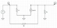
However, when added the same feedback to the equivalent z-parameters model as follows:

and did nodal analysis:
$$Nodal\ analysis:$$
$$1)\ \frac {-g_mr_πR_Ci-v_o} {R_C}=\frac {v_o-v_i} {R_f}$$
$$2)\ i=\frac {v_i-v_o} {R_f}\ +\frac {v_i} {r_π}$$
$$\Rightarrow \frac {v_o} {i}=\frac {-R_Cr_π(R_fg_m + g_mr_π - 1)} {R_C+R_f+r_π}$$
The results do not match. I really have no idea what I have missed. Any helps or pointers will be greatly appreciated!!
I write down step by step what I did for a very simple transresistance amplifier here and hope someone can point out what I did wrong:
The following is a very simple transistor I use as a transresistance amplifier example here:
and the following is the corresponding π model assume output resistance r o = ∞ just to make it simple:
I converted the circuit to a z-parameters model as follows:
with the following z-parameters value from the circuit:
$$Z_{11} = \frac {v_1} {i_1}\Bigm|_{i_2=0}=r_π$$
$$Z_{21} = \frac {v_2} {i_1}\Bigm|_{i_2=0}=-g_mr_πR_C$$
$$Z_{12} = \frac {v_1} {i_2}\Bigm|_{i_1=0}=0$$
$$Z_{22} = \frac {v_2} {i_2}\Bigm|_{i_1=0}=R_C$$
so my z-parameters model ends up like this:
When I added feedback to the π model as follows:
and did nodal analysis, I got:
$$Nodal\ analysis:$$
$$1)\ i=\frac {v_i} {r_π}+\frac {v_i-v_o} {R_f}$$
$$2)\ g_mv_i\ +\frac {v_o-v_i} {R_f}\ +\frac {v_o} {R_C}=0$$
$$\Rightarrow \frac {v_o} {i}=\frac {-R_Cr_π(g_mR_f-1)} {R_C+R_f+r_π+g_mr_πR_C}$$
However, when added the same feedback to the equivalent z-parameters model as follows:
and did nodal analysis:
$$Nodal\ analysis:$$
$$1)\ \frac {-g_mr_πR_Ci-v_o} {R_C}=\frac {v_o-v_i} {R_f}$$
$$2)\ i=\frac {v_i-v_o} {R_f}\ +\frac {v_i} {r_π}$$
$$\Rightarrow \frac {v_o} {i}=\frac {-R_Cr_π(R_fg_m + g_mr_π - 1)} {R_C+R_f+r_π}$$
The results do not match. I really have no idea what I have missed. Any helps or pointers will be greatly appreciated!!
Attachments

Last edited: