What is the maximum line current for an electric vehicle charger?

In summary: Adding a fourth in the manner that you have will certainly throw the balance off but this is not at all uncommon. As I said, basic trig should get you there.Welcome to PF. :smile:
  • #1
Skinbleu
16
0
Greetings everyone

I work at a company that sells chargers for electric vehicles and I’m working on the electrical projects.
The chargers I work with, are alternating current (AC) and the main mode here is a three-phase installation 220 V, at 7.04 kW with a current of 32 amps.

If the system only had three chargers (Q01, Q02, Q03), the current for each would be 32 amps.
Using a simulator, when adding the fourth charger(Q4), the current goes to 84 amps and I wanted to understand why.
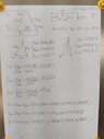
I tried to draw the three-phase circuit to make an equivalence of loads, but I couldn’t get to that value.
Does an electric car behave like a delta or star load?

Capturar.PNG
 
Physics news on Phys.org
  • #2
It's not 3 phase exactly, it's 3 single phase loads on a 3 phase line. Then adding a fourth puts two chargers on the same pair of legs.

...but I'm a mech-e so I'm nor certain how they sum in this situation so I won't guess.
 
  • Like
Likes Skinbleu
  • #3
Q01 and Q04 are simply in parallel, aren't they? (but I'm not even an eng, lol)
 
  • Haha
  • Like
Likes Juslin Waka, dlgoff and Skinbleu
  • #4
You have created an unbalanced three phase system. That is much more difficult to measure and analyze.

In an unbalanced system, we deal with positive sequence, negative sequence, and zero sequence voltages and currents (collectively called symmetrical components). In an unbalanced system, delta versus wye connections are critically important.

See https://en.wikipedia.org/wiki/Symmetrical_componentsAre you sure you want an unbalanced system?
 
  • Like
Likes Skinbleu and russ_watters
  • #5
Skinbleu said:
If the system only had three chargers (Q01, Q02, Q03), the current for each would be 32 amps.
Using a simulator, when adding the fourth charger(Q4), the current goes to 84 amps and I wanted to understand why.
You say 'the current goes to 84 amps'. What current? Measured where? Trigonometry should get you what you need to know. I'm not familiar with charging systems for electric vehicles but as @russ_watters said, you have 3 individual single phase loads on 3 different phases of a 3 phase source. To figure the currents here, forget the fact that you have electric vehicle chargers, it makes little difference. Adding a fourth in the manner that you have will certainly throw the balance off but this is not at all uncommon. As I said, basic trig should get you there.
 
  • Like
Likes russ_watters and DaveE
  • #6
Welcome to PF. :smile:

Skinbleu said:
I work at a company that sells chargers for electric vehicles and I’m working on the electrical projects.
Are you sure you aren't a student doing this as a school project? :wink:

Skinbleu said:
the main mode here is a three-phase installation 220 V, at 7.04 kW with a current of 32 amps.
So the breaker panel has 32 Amp breakers on each of the 3 phases?

Skinbleu said:
If the system only had three chargers (Q01, Q02, Q03), the current for each would be 32 amps.
Using a simulator, when adding the fourth charger(Q4),
If the breaker panel is only sized for 32A/circuit and each charger load is right at that limit already (probably a bad idea), why are you trying to add any more load? Or are you just saying that is the max available current per charger when there is only one per phase pair?
 
  • Like
Likes russ_watters, Averagesupernova and DaveE
  • #7
Skinbleu said:
Does an electric car behave like a delta or star load?
Huh? Your cars look like single phase loads to me. You're the one creating the three phases, not the cars. Or, perhaps they are three phase loads as you said, in which case your schematic makes no sense to me. I'm confused; I think it's because you are confused.

Anyway, since I don't see any neutral connection in your diagram then there is no significant difference between the delta and wye topologies. You could model it either way.

I'll second the vote to ditch the simulator and just add the currents up with simple vectors, you'll understand it better that way, and it's not difficult.
 
Last edited:
  • Like
Likes Averagesupernova
  • #8
berkeman said:
Are you sure you aren't a student doing this as a school project?
I would agree. This thread does not pass my smell test.
 
  • Like
Likes pbuk, DaveE, russ_watters and 2 others
  • #9
anorlunda said:
You have created an unbalanced three phase system. That is much more difficult to measure and analyze.

In an unbalanced system, we deal with positive sequence, negative sequence, and zero sequence voltages and currents (collectively called symmetrical components). In an unbalanced system, delta versus wye connections are critically important.

See https://en.wikipedia.org/wiki/Symmetrical_componentsAre you sure you want an unbalanced system?
It's not me, it was my client who asked. Anyway thank you for the tip, symmetrical components it's a hard way to solve it, I found a simple way.
 
  • #10
Averagesupernova said:
You say 'the current goes to 84 amps'. What current? Measured where? Trigonometry should get you what you need to know. I'm not familiar with charging systems for electric vehicles but as @russ_watters said, you have 3 individual single phase loads on 3 different phases of a 3 phase source. To figure the currents here, forget the fact that you have electric vehicle chargers, it makes little difference. Adding a fourth in the manner that you have will certainly throw the balance off but this is not at all uncommon. As I said, basic trig should get you there.
I solved it and it was not trigonometry, but thanks for your help
 
  • #11
berkeman said:
Welcome to PF. :smile:Are you sure you aren't a student doing this as a school project? :wink:So the breaker panel has 32 Amp breakers on each of the 3 phases?If the breaker panel is only sized for 32A/circuit and each charger load is right at that limit already (probably a bad idea), why are you trying to add any more load? Or are you just saying that is the max available current per charger when there is only one per phase pair?
I'm not a student. If you want, I can introduce you to my company and our projects.

The 32 amp it's to provide the 7040W for recharging.

Add one more load it's the client request.

I already solved the problem but thanks for the help.
 
  • #12
DaveE said:
Huh? Your cars look like single phase loads to me. You're the one creating the three phases, not the cars. Or, perhaps they are three phase loads as you said, in which case your schematic makes no sense to me. I'm confused; I think it's because you are confused.

Anyway, since I don't see any neutral connection in your diagram then there is no significant difference between the delta and wye topologies. You could model it either way.

I'll second the vote to ditch the simulator and just add the currents up with simple vectors, you'll understand it better that way, and it's not difficult.
Thank's for the help. This is how I solved it
 

Attachments

  • WhatsApp Image 2022-02-19 at 17.24.33.jpeg
    WhatsApp Image 2022-02-19 at 17.24.33.jpeg
    32.7 KB · Views: 104
  • #13
Averagesupernova said:
I would agree. This thread does not pass my smell test.
I'm not a student, this is a serious job, if you want I can introduce my company and our projects
 
  • #14
Skinbleu said:
Thank's for the help. This is how I solved it
So did you understand the comments earlier about an unbalanced 3-phase load?

Also, what are the breakers in the distribution panel sized for?
 
  • #15
I understood. It looks like you guys solve the unbalanced circuits in a more complicated way.

I was sizing the circuit current first, to size the breakers in the distribution panel.
 
  • #16
Skinbleu said:
I understood. It looks like you guys solve the unbalanced circuits in a more complicated way.

I was sizing the circuit current first, to size the breakers in the distribution panel.
Then you did it wrong. Typically breaker is sized to protect the wiring. If the full load current exceeds 80% of the rating of the breaker on a constant load, you have done it wrong.
 
  • #17
Skinbleu said:
I solved it and it was not trigonometry
Yes it was. Subtracting two vectors is indistinguishable from trigonometry, however you do it.

Skinbleu said:
if you want I can introduce my company
Probably better to remain anonymous in this case.
 
  • Like
  • Haha
Likes russ_watters, jrmichler, Averagesupernova and 1 other person
  • #18
Averagesupernova said:
Then you did it wrong. Typically breaker is sized to protect the wiring. If the full load current exceeds 80% of the rating of the breaker on a constant load, you have done it wrong.
I think it's a case of local regulations. In my country it works the way I explained to you, as you live in another country, there is another type of rule
 
  • #19
Skinbleu said:
I think it's a case of local regulations. In my country it works the way I explained to you, as you live in another country, there is another type of rule
And what is that rule?
 
  • Like
Likes russ_watters and berkeman
  • #20
Skinbleu said:
I think it's a case of local regulations. In my country it works the way I explained to you, as you live in another country, there is another type of rule
I would guess that makes it hard to import circuit breakers from foreign manufacturers for your installations.
 
  • Like
Likes russ_watters, Skinbleu and Averagesupernova
  • #21
Averagesupernova said:
And what is that rule?
To size breakers:

Ib<= In <= Iz

Where:
Ib - circuit current
In - breaker current
Iz - conductor currentBut it's interesting to understand how the rules are in other countries.
 
  • #22
I would be interested in seeing a chart that is accepted in your county of wire size ampacities.
 
  • Like
Likes russ_watters
  • #23
Averagesupernova said:
I would be interested in seeing a chart that is accepted in your county of wire size ampacities.
Yes, something doesn't add up here. It's hard to specify a CB that will reliably trip in fault conditions, but not nuisance trip in normal operation, when the range between ampacity and full load is narrow. So no cheap thermal CBs, I would guess.
 
  • Like
Likes russ_watters, Averagesupernova and berkeman
  • #24
The thing is, in the USA, the 'cheap' thermal breakers are appropriate for protecting the wiring. To protect a device on the circuit such as a motor, overload protection devices are used that are programmable or have an inexpensive heating element that can be replaced. Usually those devices are placed close to the place where the switching of the motor ocurrs. I would assume a battery charger for an electric vehicle would have appropriate protection on board. Silly to rely on the protection in the distribution panel.
 
  • Like
Likes Skinbleu
  • #25
Averagesupernova said:
I would be interested in seeing a chart that is accepted in your county of wire size ampacities.
Apagar5.PNG


This is the chart for wires made of PVC 750V, we also have wires made of EPR or XLPE 1 kV, but it's in another chart.
The letters above refer to installation methods, like cable tray, conduit etc.
Sorry for my terrible handwriting, I was translating for you.
 
  • #26
DaveE said:
Yes, something doesn't add up here. It's hard to specify a CB that will reliably trip in fault conditions, but not nuisance trip in normal operation, when the range between ampacity and full load is narrow. So no cheap thermal CBs, I would guess.
According to the standards that we follow in Europe, in addition to the circuit breaker, we must have a residual differential switch in the protection, which detects the leakage of current and disarms the circuit, whether due to a bad installation, cable wear or even a person getting a shock.
We also use an electrical surge protection device, which is essential to protect electrical and electronic equipment from burning out.
 
  • #27
Averagesupernova said:
The thing is, in the USA, the 'cheap' thermal breakers are appropriate for protecting the wiring. To protect a device on the circuit such as a motor, overload protection devices are used that are programmable or have an inexpensive heating element that can be replaced. Usually those devices are placed close to the place where the switching of the motor ocurrs. I would assume a battery charger for an electric vehicle would have appropriate protection on board. Silly to rely on the protection in the distribution panel.

Our charger already comes with DC and AC leakage protection, just needing a breaker to protect the wire.
 
  • #28
Here is a chart that I am more familiar with in the USA.

https://www.cerrowire.com/wp-content/uploads/2021/04/Cerrowire_Ampacity_Chart_210405.pdf

Skinbleu said:
Our charger already comes with DC and AC leakage protection, just needing a breaker to protect the wire.
Leakage protection is not overcurrent protection which is the discussion at hand. The original point still stands. In the USA a breaker in a distribution panel as well as the wire must be sized 125% of full load current unless the load is considered intermittent. The reason is to prevent nuisance tripping of the breaker as well as unnecessary heat buildup which will cause damage in the panel, breaker and wire. The breakers typically used in the USA are inexpensive yet reliable devices. They have 2 modes of protection. Thermal and magnetic. I am unaware of how breakers across the pond work but if it is allowed to run them at 100% load indefinitely then they are likely more expensive and complicated than what we use here.
 
  • Like
Likes Skinbleu and russ_watters
  • #29
Here's a nice video that shows the action inside of a breaker during overload as well as short circuit conditions. Should illustrate why the 125% rule exists.

 
  • Informative
  • Love
  • Wow
Likes Skinbleu, Tom.G and DaveE
  • #30
Averagesupernova said:
Here is a chart that I am more familiar with in the USA.

https://www.cerrowire.com/wp-content/uploads/2021/04/Cerrowire_Ampacity_Chart_210405.pdfLeakage protection is not overcurrent protection which is the discussion at hand. The original point still stands. In the USA a breaker in a distribution panel as well as the wire must be sized 125% of full load current unless the load is considered intermittent. The reason is to prevent nuisance tripping of the breaker as well as unnecessary heat buildup which will cause damage in the panel, breaker and wire. The breakers typically used in the USA are inexpensive yet reliable devices. They have 2 modes of protection. Thermal and magnetic. I am unaware of how breakers across the pond work but if it is allowed to run them at 100% load indefinitely then they are likely more expensive and complicated than what we use here.
I agree that the current must be sized 125% of full load current. We can consider the charger as a purely resistive load, since the power factor is 1.

About overcurrent protection, our circuit breakers also work in this mode: thermal and magnetic.
 
  • #31
Skinbleu said:
We can consider the charger as a purely resistive load, since the power factor is 1.
That is quite an accomplishment! So you are saying that the switching power supplies in your chargers have very effective (and complicated and expensive) Power Factor Correction input circuitry?
 
  • #32
Skinbleu said:
I agree that the current must be sized 125% of full load current.
That comment clearly contradicts:

Skinbleu said:
To size breakers:

Ib<= In <= Iz

Where:
Ib - circuit current
In - breaker current
Iz - conductor current
 
  • #33
Averagesupernova said:
That comment clearly contradicts:
I said I agree, because I think it's the right thing to do. But the norm here is different, this 25% margin is not considered
 
  • #34
berkeman said:
That is quite an accomplishment! So you are saying that the switching power supplies in your chargers have very effective (and complicated and expensive) Power Factor Correction input circuitry?
The chargers only rectify the alternating current into direct current to recharge the vehicle's battery. In this process we don't have inductive or capacitive loads.
 
  • #35
Skinbleu said:
The chargers only rectify the alternating current into direct current to recharge the vehicle's battery. In this process we don't have inductive or capacitive loads.
Doesn't matter. Your Power Factor is terrible with just a rectifier (and I don't understand how you use just a rectifier for the charger circuit anyway; that's weird).

Do you know what Power Factor means? Do you know what the voltage and current waveforms look like for a simple rectifier circuit? Why do recifiers have a poor Power Factor?
 

Similar threads

  • General Engineering
Replies
4
Views
2K
  • Electromagnetism
Replies
15
Views
1K
Replies
2
Views
2K
  • Electrical Engineering
Replies
13
Views
2K
  • Engineering and Comp Sci Homework Help
Replies
7
Views
2K
Replies
8
Views
991
  • Electrical Engineering
Replies
16
Views
3K
Replies
69
Views
7K
Replies
6
Views
1K
  • Electrical Engineering
Replies
2
Views
6K
Back
Top