Why are the voltages calculated in this way? (CE BJT Amp circuit)

In summary: Oh I see, so they are subtracting Uo from the voltage drop across RC so that the equation for Uce is more accurate.But what is the point of doing that?
  • #1
arhzz
260
52
Homework Statement
Find the missing voltages and currents
Relevant Equations
Circuit analysis
Hello!

I am having trouble with this emitter circuit.

daj mu dudu.png


I am given U0 as well as all of the resistor values and I need to calculate the following.

## I_c## ##U_{CE} ## ## U_{C} ## ## U_{a} ## ##U_{Ca}## ##U _{Re} ## Now important to note that all of these need to be calculated at the working point of the circuit.

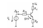
So since I am doing a DC analysis,I simplified the circuit and this is what I end up with

klosaru jedan.png


Now the Ri2 and ## U_L ## I've calculated using Thevenin circuit theorem;

$$ R_{i2} = R1||R2 $$ and $$ U_L = Uo * \frac{R2}{R1+R2} $$ ; and so far this matches the solution in the book. They simplified the circuit as well and calculated the Thevenin voltage and resistance the same way. Now I need to calculate Ib; or the base current. I used Kirchoffs law and the fact that Ic=B*Ib and I end up with this

$$ I_b = \frac{U_L-0,7}{Ri2+(B+1)Re} $$ and when I plug in the given values I get the correct answer. Plugging this Ib in the formula for Ic (as I've written it above) I get the right Ic as well, so far so good.

Now I've tried calculating Uce so the Collector-Emittter voltage and I put a loop on the right hand side of the simplified circuit and I get that

$$ U_{CE} = -U_{c} -U_{RE} + Uo $$ and to find Uc I simply used Ohm's law since I have Rc and Ic and for Ure the same, I found that the current running through Re is simply Ic+Ib and used Ohm's law. This gets me the right result as well.

Now calculating Uc gives me trouble. I simply figured it was Ohm's law but I couldnt get the right voltage. After looking at the solutions they calculated Uc like this;

$$ U_c = Uo- RcIc $$ What I don't understand why are they subracting Uo from this ? Shouldnt the voltage simply be RcIc?

Also the way they calculated ##U_{CE} ## is quite odd they calculated it like this;

$$ U_{CE} = Uo - I_c * (Rc + (1 +\frac{1}{B})Re) $$ I get the same result but why would they calculate it like this?

Also this equation is the loop equation I basically have and here the term Uc is simply resistance times voltage. Why was was Uo subtracted from this.

Thanks !
 

Attachments

  • 1667579205398.png
    1667579205398.png
    3 KB · Views: 62
Physics news on Phys.org
  • #2
UC = U0 - RCIC
What I don't understand why are they subracting Uo from this ? Shouldnt the voltage simply be RcIc?
They are NOT subtracting U0 from something, they are subtracting something from U0. That is, they start with U0 and subtract things that decrease the voltage.

What is the voltage drop across RC?
How does that compare with the equation they use?

Also the way they calculated UCE is quite odd they calculated it like this;
Again, they subtracting things from U0, leaving a result of UCE.

They combined all the voltage drops (current times resistance) into one equation and subtracted the result from U0. (See if you can name (in words) all the variables in that formula.) What is left is the C-E voltage across the transistor.

Hope this helps!

Oh, thank you for a very detailed question! You made it much easier to answer.

Cheers,
Tom
 
  • Like
Likes Steve4Physics, Lnewqban and DaveE
  • #3
Tom.G said:
They are NOT subtracting U0 from something, they are subtracting something from U0. That is, they start with U0 and subtract things that decrease the voltage.

What is the voltage drop across RC?
How does that compare with the equation they use?Again, they subtracting things from U0, leaving a result of UCE.

They combined all the voltage drops (current times resistance) into one equation and subtracted the result from U0. (See if you can name (in words) all the variables in that formula.) What is left is the C-E voltage across the transistor.

Hope this helps!

Oh, thank you for a very detailed question! You made it much easier to answer.

Cheers,
Tom
You are right my phrasing was bad they are subracting something from Uo,but my question still remains why? The voltage drop across Rc should be simply currents times resistance,why does that need to be subracted from Uo?

What is even more confusing is the second equation.What I mean is you are completely right they in how they get to the equation for Uce. I took a closer look to the equation and they did the exactly same thing I did; I did this $$ U_{CE} = - Uc - U_{RE} + Uo $$ I used kirchoff law since Uo is across the entire circuit I assumed the voltages all voltages are pointing down and the loop goes counterclockweise.

And they did exactly what you said they subracted everything from Uo to get Uce,with everything we mean every voltage that is influecing the Uce voltage.

$$ U_{CE} = Uo - I_c * (Rc + (1 +\frac{1}{B})Re) $$ This is nothing else als Uc and Ure that I have; (Uo is the same)

Because when I multiply the brackes I get this; -IcRc that should be the voltage across Uc and ##-Ic(1+\frac{1}{B})Re) ## and that is the voltage across Ure.

So if I am not mistaken in this equation Uc was simply current time resistance,why is it when we calculate it seperatly do we have to subtract that voltage drop from Uo.Also also; I've plug in the values of the voltages according to the textbook. According to them;
##U_{CE} = 5,32V ## ##U_{C} = 6,21V ## ##U_{RE} = 0,88V ## and Uo = 15V

Now for my Uc I get = 8,79V

Now assuming Kirchoffs Loop law need to be obeyed like in usual circuits it should be true that

$$ 0= Uc + U_{RE} +U_{CE} - Uo $$ If you plug in the given values this is not true,but if you plug in my value it is 14.99 -15; and to note is I have not paid that much attention to rounding the numbers.

Could it be possible that it is a fault in the script? These are by no means perfect and we have had some errors occur before.

Thanks!

P.S Detailed questions are a must at StackOverflow.
 
  • #4
arhzz said:
The voltage drop across Rc should be simply currents times resistance,why does that need to be subracted from Uo?
Because they asked for the voltage at the Collector, they did NOT ask for the voltage drop across RC... but you Do need the drop across RC to find the Collector voltage. (Just like a 2-resistor voltage divider, if you know the supply voltage and the drop across the high-side resistor you can find the voltage at the top of the low-side resistor.)

arhzz said:
Because when I multiply the brackes I get this; -IcRc that should be the voltage across Uc and ##-Ic(1+\frac{1}{B})Re) ## and that is the voltage across Ure.

So if I am not mistaken in this equation Uc was simply current time resistance,why is it when we calculate it seperatly do we have to subtract that voltage drop from Uo.
See the paragraph above. Both parts of the problem calculate the Collector voltage, UC. The first calculation was finding the drop across RC and subtracting that drop form U0, giving UC.

The second calculation was finding the drop across RE and the transistor. Since the reference for this calculation was Ground (or circuit common), you calculated the Collector voltage directly.

arhzz said:
Also also; I've plug in the values of the voltages according to the textbook. According to them;
##U_{CE} = 5,32V ## ##U_{C} = 6,21V ## ##U_{RE} = 0,88V ## and Uo = 15V

Now for my Uc I get = 8,79V
I think you are confusing UC and the voltage drop across RC. UC is the supply voltage minus the drop across RC.

Cheers,
Tom
 
  • Like
Likes arhzz
  • #5
Tom.G said:
Because they asked for the voltage at the Collector, they did NOT ask for the voltage drop across RC... but you Do need the drop across RC to find the Collector voltage. (Just like a 2-resistor voltage divider, if you know the supply voltage and the drop across the high-side resistor you can find the voltage at the top of the low-side resistor.)See the paragraph above. Both parts of the problem calculate the Collector voltage, UC. The first calculation was finding the drop across RC and subtracting that drop form U0, giving UC.

The second calculation was finding the drop across RE and the transistor. Since the reference for this calculation was Ground (or circuit common), you calculated the Collector voltage directly.I think you are confusing UC and the voltage drop across RC. UC is the supply voltage minus the drop across RC.

Cheers,
Tom
Oooooh okay that makes sence. I was calculating correctly but not what whas asked from me, I was not aware that Collector voltage and the drop at Rc are not the same. Thank you Tom!

But I have another question. I have calculated all that is asked from me and what we can see in this handwritten circuit (working point) but in the solutions they also calculated Ua and Uca. Ua is the output voltage and it is 0 and Uca=Uc. I do not understand where this comes from? Im aware that these come from the original circuit but why? In the solution for all of the voltages in the working point was the original circuit simplified just like I have it and there are no capacitors there and no output voltage. How do they find these voltages?
 
  • #6
arhzz said:
they also calculated Ua and Uca. Ua is the output voltage and it is 0 and Uca=Uc. I do not understand where this comes from? Im aware that these come from the original circuit but why?
Hope it's OK to chip-in.

Refer to the original (complete) circuit. The operating point (DC conditions) is a steady-state, so there are no currents through the capacitors (even though the capacitors are charged).

As a result, there can be no current through ##R_L##. This means the voltage across ##R_L## is zero. This voltage is the same as the output voltage, i.e. ##U_a=0##.

The right side of capacitor-a has potential = 0 (because ##U_a = 0##). The left side of capacitor-a has the same potential as the collector (##U_C##)

Potential difference across capacitor = ##U_{Ca} = U_C - 0 = U_C##

Edit - typo' corrected.
 
Last edited:
  • Like
Likes Tom.G and arhzz
  • #7
Steve4Physics said:
Hope it's OK to chip-in.

Refer to the original (complete) circuit. The operating point (DC conditions) is a steady-state, so there are no currents through the capacitors (even though the capacitors are charged).

As a result, there can be no current through ##R_L##. This means the voltage across ##R_L## is zero. This voltage is the same as the output voltage, i.e. ##U_a=0##.

The right side of capacitor-a has potential = 0 (because ##U_a = 0##. The left side of capacitor-a has the same potential as the collector (##U_C##)

Potential difference across capacitor = ##U_{Ca} = U_C - 0 = U_C##
Perfect thank you Steve!
 
  • Like
Likes Steve4Physics
  • #8
@arhzz,
Hi - may I ask you if you know the value of B=Ic/Ib ?
I am asking this because you have assumed that the BJT will work as a current amplifier. Therefore, you need the quantity B.
 
  • #9
LvW said:
@arhzz,
Hi - may I ask you if you know the value of B=Ic/Ib ?
I am asking this because you have assumed that the BJT will work as a current amplifier. Therefore, you need the quantity B.
B was given a value of 300
 

1. Why are the voltages calculated in this way?

The voltages in a common emitter (CE) bipolar junction transistor (BJT) amplifier circuit are calculated using Kirchhoff's voltage law and Ohm's law. This allows us to determine the voltage drops across each component in the circuit and ensure that the circuit is functioning properly.

2. What is Kirchhoff's voltage law?

Kirchhoff's voltage law states that the algebraic sum of the voltage drops in a closed loop circuit must equal zero. In other words, the total voltage supplied by the power source must equal the total voltage drops across all components in the circuit.

3. How does Ohm's law apply to this circuit?

Ohm's law states that the current flowing through a conductor is directly proportional to the voltage and inversely proportional to the resistance. In a CE BJT amplifier circuit, the voltage drops across each component can be calculated using Ohm's law (V=IR) and the known values of current and resistance.

4. What is the significance of calculating voltages in this way?

Calculating voltages in a CE BJT amplifier circuit allows us to ensure that the circuit is functioning properly and to troubleshoot any issues that may arise. It also allows us to determine the voltage gain of the circuit, which is an important characteristic for amplifiers.

5. Are there any limitations to this method of calculating voltages?

While Kirchhoff's voltage law and Ohm's law are fundamental principles in circuit analysis, they may not always accurately represent the behavior of real-world circuits. Factors such as parasitic capacitances and inductances can affect the voltage drops in a circuit, and these must be taken into consideration when analyzing a CE BJT amplifier circuit.

Similar threads

  • Engineering and Comp Sci Homework Help
Replies
5
Views
881
  • Engineering and Comp Sci Homework Help
Replies
1
Views
1K
  • Engineering and Comp Sci Homework Help
Replies
4
Views
1K
  • Engineering and Comp Sci Homework Help
Replies
3
Views
817
  • Engineering and Comp Sci Homework Help
Replies
28
Views
2K
  • Engineering and Comp Sci Homework Help
Replies
7
Views
905
  • Engineering and Comp Sci Homework Help
Replies
10
Views
2K
  • Engineering and Comp Sci Homework Help
Replies
5
Views
1K
Replies
10
Views
1K
  • Engineering and Comp Sci Homework Help
Replies
3
Views
1K
Back
Top