Tygra
- 55
- 8
- Homework Statement
- Calculating Deflections
- Relevant Equations
- In question
Dear all
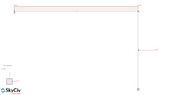
I am trying to find the support reactions on the following structure:

The frame member in the horizontal is 8m long and in the vertical the member is 5m.
To do this I am using the force method (or unit load method or virtual work method).
Firstly, I removing the redundants at the pinned support to make a statically determinant frame as shown below:

Next, I apply units loads in place of the pinned support that looks like this:

Firstly, lets consider the horizontal unit load. I need the displacement in the parallel and perpendicular directions as a result of this horizontal unit load.
Calculating the horizontal displacement as a result of this load is no problem. It is simply the sumof the integration of the bending moments.

So, the moment functions are: Mx = -1*x and Mx = 5. Hence, the integration to compute the delection in the horizontal direction is

The area where I am a little stuck is computing the vertical deflection as a result of the horizontal unit load.
If you see here from the software the vertical displacement is 4.074 mm.

So my question is: how do I calculate this displacement using the force method?
Many thanks in advance.
I am trying to find the support reactions on the following structure:
The frame member in the horizontal is 8m long and in the vertical the member is 5m.
To do this I am using the force method (or unit load method or virtual work method).
Firstly, I removing the redundants at the pinned support to make a statically determinant frame as shown below:
Next, I apply units loads in place of the pinned support that looks like this:
Firstly, lets consider the horizontal unit load. I need the displacement in the parallel and perpendicular directions as a result of this horizontal unit load.
Calculating the horizontal displacement as a result of this load is no problem. It is simply the sumof the integration of the bending moments.
So, the moment functions are: Mx = -1*x and Mx = 5. Hence, the integration to compute the delection in the horizontal direction is
The area where I am a little stuck is computing the vertical deflection as a result of the horizontal unit load.
If you see here from the software the vertical displacement is 4.074 mm.
So my question is: how do I calculate this displacement using the force method?
Many thanks in advance.