Discussion Overview
The discussion revolves around the amplitude of an analog filter, focusing on the calculations involving reactance, impedance, and the behavior of circuits containing inductors and capacitors. Participants explore various aspects of circuit analysis, including potential dividers and resonance effects.
Discussion Character
- Technical explanation
- Mathematical reasoning
- Debate/contested
Main Points Raised
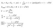
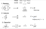
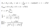
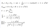
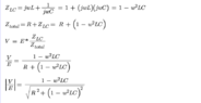
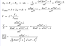
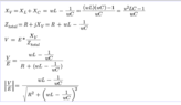
- Some participants question the calculation of reactance, particularly the sign of capacitive reactance (XC) and its role in the total impedance.
- There are discussions about the implications of resonance in circuits, with mentions of a deep notch in voltage at resonant frequencies.
- Participants express confusion regarding the treatment of imaginary and real components in impedance calculations, emphasizing the need for careful handling of complex numbers.
- Some participants suggest that the removal of imaginary components and the handling of signs in equations need to be approached methodically.
- There are repeated references to the need for understanding the orthogonal nature of real and imaginary axes in complex impedance.
- Several participants provide links to external resources for further clarification on reactance and complex numbers.
Areas of Agreement / Disagreement
Participants do not reach a consensus, as there are multiple competing views on the correct approach to calculating reactance and impedance. Confusion and uncertainty persist regarding the treatment of complex numbers and the implications of resonance.
Contextual Notes
Limitations include potential misunderstandings of complex arithmetic and the need for clarity on the definitions of reactance and impedance. Some calculations remain unresolved, and assumptions about the treatment of signs and components are not fully agreed upon.