Anti vandal led button MOFSET question

  • Thread starter Thread starter BaDaBooMM
  • Start date Start date
  • Tags Tags
    Led
Join the discussion
Ask a follow-up here, or get your own question answered by working scientists, mathematicians and engineers — people, not an autocomplete.
Real named experts · corrections over time · the nuance an AI answer skips
2 replies · 2K views
BaDaBooMM
Messages
4
Reaction score
0
I'm a total noob when it comes to electronics and you are going to lol at me. Please don't lol too hard.
because I'm not really good at this stuff its going to be hard for me to explain but Ill do my best.

I have circuit board for an ecig that I want to use a led anti vandal switch for it like this one http://www.ebay.co.uk/itm/12mm-LED-Illuminated-Vandal-Proof-Anti-Vandal-Momentary-Push-Button-Switch-/331283052848?_trksid=p2054897.l4275

So what's the problem ? I only want the led to light up when the button is pressed and go off when the the button is released.

What I think I need is a MOFSET that can monitor the drain from the battery ??

As you can see my wiring diagrams if you can even call them that are for children. I've got this far and now I'm stuck.
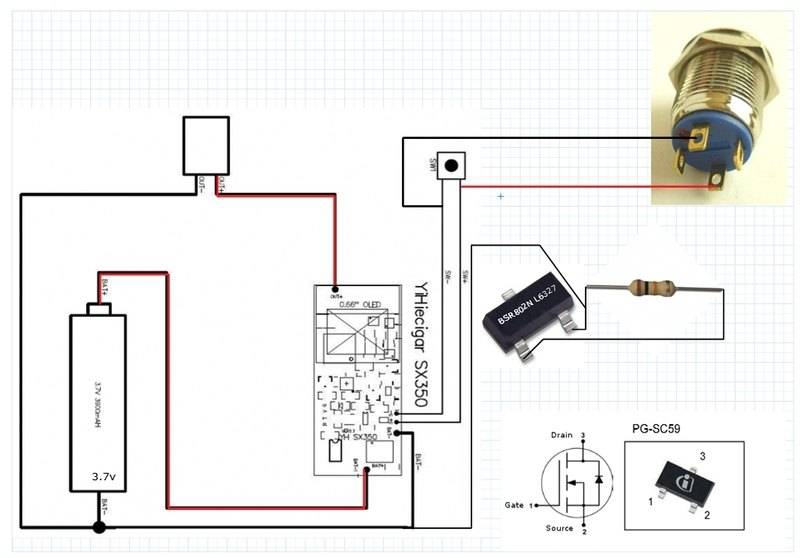
Imhgjghage2.jpg


Any help would be much appreciated :)
 
Last edited by a moderator:
Engineering news on Phys.org
That's a pretty confusing pushbutton + LED combination. From the e-Bay description, they say they used a 4.2V source and a 470k resistor to light the LED, which makes no sense at all. That's way too big of a resistor.

And going to the home website for the manufacturer, it looks like you need to specify what voltage you are going to put across the +/- terminals for the LED, which would imply that the current-limiting resistor is already part of the pushbutton housing:

http://www.onpow.com/en/product/product1351.html

The lowest LED voltage option they list is 6V, so you probably can't light the LED with just your 3.7V e-cigarette battery.

The simplest way to light an LED when you press a button to turn on your e-cigarette circuit would be to use a double-pole, single-throw pushbutton, and connect power to an LED through a current-limiting resistor with the second pole of the switch.
 
berkeman said:
That's a pretty confusing pushbutton + LED combination. From the e-Bay description, they say they used a 4.2V source and a 470k resistor to light the LED, which makes no sense at all. That's way too big of a resistor.

And going to the home website for the manufacturer, it looks like you need to specify what voltage you are going to put across the +/- terminals for the LED, which would imply that the current-limiting resistor is already part of the pushbutton housing:

http://www.onpow.com/en/product/product1351.html

The lowest LED voltage option they list is 6V, so you probably can't light the LED with just your 3.7V e-cigarette battery.

The simplest way to light an LED when you press a button to turn on your e-cigarette circuit would be to use a double-pole, single-throw pushbutton, and connect power to an LED through a current-limiting resistor with the second pole of the switch.

Thanks for help but I'm lost :)

This is what was posted in another forum but I don't really understand it.

You need an N fet like this one Infineon BSR802N L6327

It's not a complicated task to switch power to the battery monitor, just use a small power MOSFET in an SOT23 package which is not terribly small or hard to work with. The MOSFET gate is driven by the atomizer. The drain and source of the MOSFET switch the power supply to the monitor.

To work with the logic polarity of the atomizer (high = on, low = off) you need to use an N-channel MOSFET configured as a low side switch. The low side (battery negative) for the monitor is switched, not the high side (battery positive). The connection is as follows;

Ground for the detector connected to NMOS drain.
Battery negative connected to NMOS source.
A pull-down resistor connected from gate to source.
Atomizer positive connected to the gate.

That FET you selected should do the job just fine. You could even go as high as a 1/2 Ohm "on" resistance since the currents required to power the monitor are pretty low reducing the effect of switch resistance on voltage drops.

Pull down resistor values are not critical, anything between 4.7k and 47k should be fine. 10k would be a typical value.

I was following the instructions in the qouted text above and got stuck.

Imafghfgge3.jpg
 
Last edited: