Calculate the stresses in this 4-member wooden frame

  • Thread starter Thread starter Vladimir_Kitanov
  • Start date Start date
  • Tags Tags
    Frame
Click For Summary

Discussion Overview

The discussion revolves around the calculation of stresses in a four-member wooden frame, focusing on the forces acting at various points and the assumptions regarding their parallelism. Participants explore the implications of these forces on the structural integrity and methods for solving the problem, including considerations of bending and shear loads.

Discussion Character

  • Technical explanation
  • Debate/contested
  • Mathematical reasoning

Main Points Raised

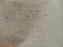
  • Some participants question why the force at point D needs to be parallel to the forces at points E and F, suggesting that rotation around D would occur otherwise.
  • Others argue that the parallelism of forces at D, E, and F is a consequence of the coincidental direction of the only other forces acting on member DEF.
  • There is a proposal to solve the problem without assuming that forces are parallel, with some participants expressing belief that it is possible.
  • One participant mentions difficulties in solving the problem, consistently encountering two unknowns and one equation, which they find impossible to resolve.
  • Another participant suggests that the two horizontal members are not purely under compression or tension, indicating that they are supporting bending and shear loads.
  • There is a discussion about using moment calculations at intermediate points to estimate loads and stresses on the members.
  • One participant asserts that they have proven forces must be parallel for the system to be static, while another questions the necessity of this proof for solving the original problem.
  • Confusion arises regarding the need for proof of parallel forces, with participants expressing differing views on its relevance to solving the problem.

Areas of Agreement / Disagreement

Participants express differing opinions on the necessity of assuming parallel forces in solving the problem. While some believe it is essential, others argue that it may not be required. The discussion remains unresolved regarding the implications of these assumptions on the calculations.

Contextual Notes

Some participants note that the structure may not be statically determinate and that deformation of members needs to be accounted for in the analysis. There are references to specific problem-solving techniques and external resources, but no consensus on the approach is reached.

Vladimir_Kitanov
Messages
44
Reaction score
14
Misplaced Homework Thread
Screenshot_20221114_190613_com.google.android.apps.docs.jpg
Screenshot_20221114_190619_com.google.android.apps.docs.jpg

Why force at D need to be parallel to force at E and F?
 
Physics news on Phys.org
Vladimir_Kitanov said:
Why force at D need to be parallel to force at E and F?
Because otherwise there would be rotation around D.
 
Vladimir_Kitanov said:
Why force at D need to be parallel to force at E and F?
Force at D does not need to be, it happens to be parallel as a consequence of the coincidential direction of the only other forces acting on that member DEF.

BCEF forms a quadrilateral of which only the opposite sides and angles are equal, making the directions of forces at D, E and F parallel to each other.
 
Can this be solved without assuming that forces are parallel?
 
Vladimir_Kitanov said:
Can this be solved without assuming that forces are parallel?
I believe so.
Have you done any solution work that we could see?
 
Lnewqban said:
I believe so.
Have you done any solution work that we could see?
How ever I tried I did not managed to solve it.
 
Lnewqban said:
I believe so.
Have you done any solution work that we could see?
I brake that in pieces but always get 2 unknowns and 1 equation.
That is impossible to solve.
 
Vladimir_Kitanov said:
I brake that in pieces but always get 2 unknowns and 1 equation.
That is impossible to solve.
Could you please show us what you have done so far?
 
Lnewqban said:
Could you please show us what you have done so far?
I can't send picture now it say that I have low memory
 
  • #10
IMG_20221115_192800.jpg
IMG_20221115_192814.jpg
IMG_20221115_192826.jpg
 
  • #11
Thank you!
Hard to see, but I will try a little later.
 
  • #12
Lnewqban said:
Thank you!
Hard to see, but I will try a little later.
Okay thanks
 
  • #14
Sorry for later than promised response.
The two horizontal members, AC and DF are not working purely under compression or tension, like it would happen in a truss.
This is an armature, in which some members are supporting bending and shear loads.
That is the case for those two horizontal members.

You could try estimating those loads by calculating moments and forces also about the intermediate points B and E respectively.
The reactions at those points, aligned with the 3-4-5 triangles, would be the asked axial loads of members CF and BE (both under pure axial loads, no bending or shear).

The rest would be to estimate the stresses that those axial loads impose on the 2x4 cross sections.

000-three-force-member.gif
 
  • #15
Lnewqban said:
Sorry for later than promised response.
The two horizontal members, AC and DF are not working purely under compression or tension, like it would happen in a truss.
This is an armature, in which some members are supporting bending and shear loads.
That is the case for those two horizontal members.

You could try estimating those loads by calculating moments and forces also about the intermediate points B and E respectively.
The reactions at those points, aligned with the 3-4-5 triangles, would be the asked axial loads of members CF and BE (both under pure axial loads, no bending or shear).

The rest would be to estimate the stresses that those axial loads impose on the 2x4 cross sections.

View attachment 317262
Still can't do that.
IMG_20221116_195714.jpg
IMG_20221116_195721.jpg
 

Attachments

  • IMG_20221116_195707.jpg
    IMG_20221116_195707.jpg
    36.1 KB · Views: 153
  • #16
Did you solve it?
 
  • #17
Vladimir_Kitanov said:
Did you solve it?
No, sorry, I have had no time to properly do it.
Do you know the official responses?

Now you have two more moment equations to use (about B and E joints).

If you can, please, study problem 003 of link provided in post #13 above.
 
  • #18
It looks like your structure is not statically determinate; e.g., you could make the support at D a roller support to eliminate Dy, and the structure would still be stable. To solve the original problem, you would need to account for the deformation of each member. This would not be a fun problem to solve by hand. You could solve this pretty quickly using an FEA program if you have one available.
 
  • #19
I think that I proved that forces must be parallel if system is in static.
IMG_20221121_175817.jpg
 
  • Like
Likes   Reactions: Lnewqban
  • #20
Vladimir_Kitanov said:
I think that I proved that forces must be parallel if system is in static.
Do you need to do that to solve the original question about maximum internal loads of members BE and CF?
 
  • #21
Lnewqban said:
Do you need to do that to solve the original question about maximum internal loads of members BE and CF?
No.
I just need proof 😂
 
  • #22
Vladimir_Kitanov said:
No.
I just need proof 😂
I see, but why?
Aren’t you only trying to solve the problem as described in the original post?
Sorry, I am confused.
 
  • #23
Lnewqban said:
I see, but why?
Aren’t you only trying to solve the problem as described in the original post?
Sorry, I am confused.
I tried to solve it without assuming that forces are parallel, but failed.
I beleaved that it is true but i wanted to see that proof.
 
  • #24
OK, let’s start from scratch.
In general terms, what have you learned about solving structures so far?
 
  • #25
Lnewqban said:
OK, let’s start from scratch.
In general terms, what have you learned about solving structures so far?
I already knowed how to solve those problems but that confused me.
That is first time I needed to know that forces are parallel.
 

Similar threads

  • · Replies 0 ·
Replies
0
Views
2K
  • · Replies 10 ·
Replies
10
Views
2K
  • · Replies 2 ·
Replies
2
Views
3K
  • · Replies 3 ·
Replies
3
Views
2K
  • · Replies 7 ·
Replies
7
Views
3K
  • · Replies 13 ·
Replies
13
Views
4K
  • · Replies 5 ·
Replies
5
Views
2K
  • · Replies 5 ·
Replies
5
Views
2K
Replies
18
Views
3K
  • · Replies 3 ·
Replies
3
Views
3K