Vladimir_Kitanov
- 44
- 14
Misplaced Homework Thread
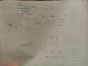
Why force at D need to be parallel to force at E and F?
The discussion revolves around the calculation of stresses in a four-member wooden frame, focusing on the forces acting at various points and the assumptions regarding their parallelism. Participants explore the implications of these forces on the structural integrity and methods for solving the problem, including considerations of bending and shear loads.
Participants express differing opinions on the necessity of assuming parallel forces in solving the problem. While some believe it is essential, others argue that it may not be required. The discussion remains unresolved regarding the implications of these assumptions on the calculations.
Some participants note that the structure may not be statically determinate and that deformation of members needs to be accounted for in the analysis. There are references to specific problem-solving techniques and external resources, but no consensus on the approach is reached.