pedromatias
- 3
- 1
- Homework Statement
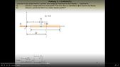
- A bar of length l has charge Q that is linearly distributed, with constant charge density λ. There is a point P at distance D from the center of mass of the bar, and P is in the same axis as the bar. Knowing the electric field, calculate the electric potential at P using a line integral. See figure.
- Relevant Equations
- The difference of potential between two points is symmetric to the line integral between those two points of the dot product between the electric field and the line.
So, I am able to calculate the electric potential in another way but I know that this way is supposed to work as well, but I don't get the correct result.
I calculated the electric field at P in the previous exercise and its absolute value is $$ E = \frac {k Q} {D^2-0.25*l^2} $$ This is correct as per the solution. From the figure, we can see that the direction of the electric field at P is that of the negative x direction.
So, to calculate the electric potential I took advantage of the fact that at infinite the potential is zero and did
$$ V_P = \int_D^{\infty} \frac {k Q} {r^2-0.25*l^2} \, dr$$
However, this integral does not give the correct result. I inserted it into integral calculator and the result was not the correct one, which is
$$ k \lambda \ln \frac {D+\frac{l}{2}} {D-\frac{l}{2}}$$
I don't understand what I am doing incorrectly. My reasoning is that I have the expression for the Electric field in a point at a distance ##r## in the axis of ##P##, and that Electric field points in the same direction as the straight line path from ##P## to ##\infty##, so the dot product is the magnitude of the electric field.
The way I solved it correctly and which gives me the right solution is, where ##x## is the distance from P,
$$ dv = k \frac {dq}{x}$$
$$ dv = k \lambda \frac {dx}{x}$$
$$ V = \int_{D-0.5l}^{D+0.5l} \frac {k \lambda} {x} \, dx $$
$$ V = k \lambda \ln \frac {D+\frac{l}{2}} {D-\frac{l}{2}}$$