Calculating Input impedance of a CC amplifier

Click For Summary

Discussion Overview

The discussion revolves around calculating the input impedance of a Common Collector (CC) amplifier using two different methods: a manual series resistor method and a plot method using LTspice. Participants explore the discrepancies between the impedance values obtained from these methods and the implications of circuit configuration on the results.

Discussion Character

  • Technical explanation
  • Debate/contested
  • Mathematical reasoning

Main Points Raised

  • The original poster (OP) calculates input impedance using a series resistor method, yielding a value of 1001.5257 Ω, while the LTspice plot method gives 1909.066 Ω.
  • Some participants suggest that the configuration of the 2N3906 transistor may be incorrect, proposing that inverting it could affect the impedance calculations.
  • One participant notes that inverting the power supply results in an input impedance of 1030 Ω, which they argue is closer to the OP's calculated value.
  • Another participant points out that the circuit was initially described as a Common Collector configuration but appears to be operating as a Common Emitter circuit, leading to confusion in results.
  • One participant reports obtaining a consistent input impedance of 7.1093266 kΩ regardless of the method used, emphasizing the importance of considering voltage and current as vectors in calculations.
  • A participant calculates the complex impedance based on frequency and transistor beta, arriving at a value of 7127.45 Ω, which aligns closely with the LTspice result.
  • Clarifications are made regarding the notation "1k0," which represents 1000 ohms, and its relevance in the impedance calculations.
  • Another participant provides a detailed breakdown of the impedance calculation, incorporating the transistor's beta and the resistances in the circuit.

Areas of Agreement / Disagreement

Participants express differing views on the correct configuration of the transistor and the resulting input impedance values. There is no consensus on why the impedance values differ between methods, and multiple competing interpretations of the circuit's behavior are present.

Contextual Notes

Participants highlight potential issues with circuit configuration and assumptions regarding the transistor's operation mode, which may affect the accuracy of the impedance calculations. The discussion also indicates that the calculations depend on specific parameters such as frequency and transistor beta.

brainbaby
Messages
232
Reaction score
5
TL;DR
comparing input impedance calculated manually and via ltspice
Hi friends,

Here is a CC amplifier
The objective is to calculate its input impedance.
Two ways are employed.
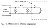
*calculating input impedance using series resistor method (manual method) (refer first two attachment)
V1 = 1mV = 0.001 V
V2 = 656.4129mV = 0.6564129 V
R = 1K
Iin = 343.83207µA = 0.0003438 A
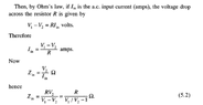
Zin = R / V1/V2 -1
Zin = 1001.5257 Ohm (input impedance)

The value on Zin found out by series resistor method is 1001.5257 Ω at 10khz
But Zin calculated via plot method (ltspice) i.e Vtest/ Itest is 1909.066 Ω at 10khz for reference

My query is that both the method should yield the same value for Zin.
Why do the Zin values calculated by both methods differ?


Screenshot 2021-10-15 at 11.05.24 PM.png

fig- input impedance via Vtest/ Itest (ltspice plot method)

Note: attached are two .asc files which represent the calculation of input impedance using series resistor manual method & plot method i.e Vtest/ I test.


Thanks
 

Attachments

Last edited:
Engineering news on Phys.org
Judging by your power supply polarity, I think the 2N3906 in your files.asc.txt need to be inverted.
Ctrl R twice, followed by ctrl E.
Let us know if that does not make a difference.
 
  • Like
Likes   Reactions: brainbaby
Baluncore said:
Judging by your power supply polarity, I think the 2N3906 in your files.asc.txt need to be inverted.
Ctrl R twice, followed by ctrl E.
Inverting 2N3906 yield input impedance way out of proportion to 8kΩ
however, inverting the power supply brings the value of input impedance down to 1030Ω or 1.03kΩ around 10khz which seems very much reasonable near to my calculated value of 1001 Ω. Isn't?

reverse pol.png


rev pnp.png
 
B..B..B..But the OP specified a Common Collector ckt. (Emitter Follower), it is now a Common Emitter ckt. o0)

The original ckt was using the transistor in 'inverted' (? 'inverse') mode, swapping the Emitter and Collector. They can operate that way, but not very well.

No wonder the results were confusing.
 
  • Like
Likes   Reactions: brainbaby
Your first figure shows a common emitter with a crazy bias network, not a CC amplifier.

Your second figure looks better.

I get Zin = 7.1093266 k ohm, no matter how I do it.
Plot "1k0*V(V2)/V(v1,v2)" or "V(V2)/I(Rs)" to get identical results.

Don't forget that the voltages and currents are vectors. You must allow for phase if you do the computation from the magnitude only.
 
  • Like
Likes   Reactions: brainbaby
If I assume frequency = 10 kHz, and the 2N3906 beta is 200, then compute complex impedance as I work my way from right to left across the ladder diagram, I get; Zin = 7127.45 ohms.
That compares well with LTspice Zin = 7109.3266 ohms.
 
  • Like
Likes   Reactions: brainbaby
Baluncore said:
1k0*V(V2)/V(v1,v2)
I didn't comprehend this. what does 1k0 signify here?
 
The current i, through the 1k0 resistor drops a voltage = i * 1000 = V(V1,V2).
We must divide the V(V1,V2) by 1000 = 1k0 to scale Zin.
Since it is inverse we multiply.

Here is the impedance at 10 kHz, with beta = 193.1
Code:
  Impedance       Resistance     Reactance
 Initial RL   (  +1000.000000    +0.000000 j ) ohms
 Series C1    (  +1000.000000    -1.591549 j ) ohms
 Parallel R3  (   +500.000317    -0.397887 j ) ohms
 Beta = 193.1 ( +96550.061141   -76.832000 j ) ohms
 Parallel R1  ( +24593.986082    -4.985338 j ) ohms
 Parallel R2  (  +7109.324214    -0.416575 j ) ohms
 Series C2    (  +7109.324214   -16.332069 j ) ohms
 Magnitude Zin = +7109.342973 ohms
 LTspice   Zin =  7109.3266 ohms
 
  • Like
Likes   Reactions: brainbaby
  • #10
brainbaby said:
I didn't comprehend this. what does 1k0 signify here?
1k0 is 1000 ohms. Have a look at: https://en.wikipedia.org/wiki/Common_collector

For a sanity check calculation using figure 3 of the wiki page we have Rin = β*RE for the transistor and RE alone.

Your circuit has R3 = 1000 ohms (1k0) in parallel with RL = 1000 ohms; that gives RE = 500 ohms for the load on the emitter. From that using Rin = β*RE with β ~ 200, we get Rin = 100000 ohms at the base. But the two resistors of the bias network are in parallel with that, so finally Zin of the total circuit is given by
Zin = R1 || R2 || β*RE which is approximately 7127 ohms.
 
  • Like
Likes   Reactions: brainbaby

Similar threads

Replies
10
Views
3K
  • · Replies 9 ·
Replies
9
Views
8K
  • · Replies 1 ·
Replies
1
Views
4K
  • · Replies 38 ·
2
Replies
38
Views
9K
  • · Replies 4 ·
Replies
4
Views
2K
  • · Replies 3 ·
Replies
3
Views
3K
  • · Replies 1 ·
Replies
1
Views
2K
  • · Replies 15 ·
Replies
15
Views
3K
  • · Replies 2 ·
Replies
2
Views
2K
  • · Replies 5 ·
Replies
5
Views
4K