a_c_e
- 3
- 0
May I start by saying hello to all and that I have visited the site before, but have yet to create an account until now. With that said, I am having difficulty calculating proper numbers for a project I am designing. Mind you, it has been about seven years since I was in any physics or "advanced" physics classes; my job more so pertaining to electrical calculations.
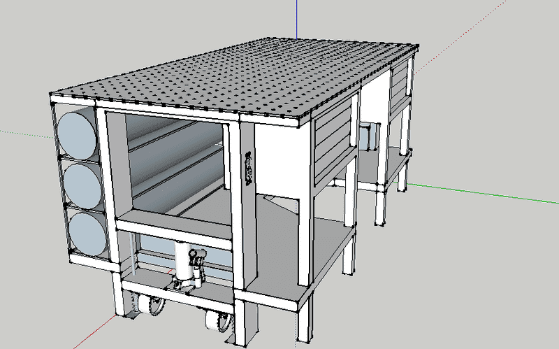
Intro: The idea is a welding workbench with a tilt top on it. the top is 72" wide, 36" deep and 3.25" tall. There will be three hinges welded across the front edge. The combined weight of the 1/4" sheet on top, as well as the 3" of subframing will be approximately 300lbs (I'll explain why an approximation is acceptable in a moment). Now, in theory, the 300lbs is applied at the center of the bench top. I need the lift force to exceed this however because I will be jigging framing and parts on the workbench surface before raising the bench angle. Hence, the mostly irrelevant inaccuracy of the weight aforementioned.
Problem: Now, if I could find a reasonably priced linear actuator that had a 51" path of travel (hypotenuse of bench depth) and more than capable lift force, then I would not be here. However... I can find a reasonably priced 30" path of travel linear actuator (only needing 25" if I lift from the center of the bench top). This creates a substantially higher lift force though. So, in hopes of lessening the required force, I intend on adding two gas springs (dampers/struts) to aid in lifting. I am not entirely sure that I know how to calculate how much the gas springs will actually lift if they are mounted at hypothetical point A or point B, given a 250lb max lift force for the gas springs. I also plan on adding "stands" for 30, 45, 60 and 90 degrees (braces I can rest the bench on to alleviate the stress continuously being on the actuator and gas springs).
Here is an image I took of the draft (I have yet to add the subframe for the bench top), but it should give a better idea of what I am trying to explain.
As I am sure there may be more questions to better help those who assist me, please feel free to ask for any further elaboration. Thank you in advance.
Intro: The idea is a welding workbench with a tilt top on it. the top is 72" wide, 36" deep and 3.25" tall. There will be three hinges welded across the front edge. The combined weight of the 1/4" sheet on top, as well as the 3" of subframing will be approximately 300lbs (I'll explain why an approximation is acceptable in a moment). Now, in theory, the 300lbs is applied at the center of the bench top. I need the lift force to exceed this however because I will be jigging framing and parts on the workbench surface before raising the bench angle. Hence, the mostly irrelevant inaccuracy of the weight aforementioned.
Problem: Now, if I could find a reasonably priced linear actuator that had a 51" path of travel (hypotenuse of bench depth) and more than capable lift force, then I would not be here. However... I can find a reasonably priced 30" path of travel linear actuator (only needing 25" if I lift from the center of the bench top). This creates a substantially higher lift force though. So, in hopes of lessening the required force, I intend on adding two gas springs (dampers/struts) to aid in lifting. I am not entirely sure that I know how to calculate how much the gas springs will actually lift if they are mounted at hypothetical point A or point B, given a 250lb max lift force for the gas springs. I also plan on adding "stands" for 30, 45, 60 and 90 degrees (braces I can rest the bench on to alleviate the stress continuously being on the actuator and gas springs).
Here is an image I took of the draft (I have yet to add the subframe for the bench top), but it should give a better idea of what I am trying to explain.
As I am sure there may be more questions to better help those who assist me, please feel free to ask for any further elaboration. Thank you in advance.