Current through an inductor as a function of time

AI Thread Summary
The discussion revolves around calculating the current through an inductor in a given circuit after a switch is closed. The initial approach involved finding the equivalent resistance using Thevenin's theorem, but the user initially miscalculated the steady-state current through the inductor. After applying Kirchhoff’s laws and correcting the calculations, the final expression for the current as a function of time was derived as i(t) = V/(5R)(1 - e^(-25Rt/12L)). The importance of distinguishing between different resistances and using correct notation was emphasized to avoid confusion. The conversation highlights the significance of understanding Thevenin's theorem in transient analysis for circuits involving inductors.
palaphys
Messages
235
Reaction score
12
Homework Statement
Find the current through the inductor as a function of time, if the switch is closed at t=0.
Relevant Equations
V= Ldi/dt
1753609451714.webp
this is the circuit given. I have marked points A,B C and D.

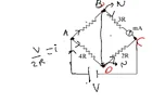
First, my attempt is to find the time constant for the circuit. For this, my approach will be to remove all voltage sources and replace them with their internal resistance, so that I can find the equivalent resistance between B and D.
1753609723570.webp

hence the modified circuit. now clearly,
$$V_A= V_C$$ as they are connected by a wire. So I think that the R and 3R are in parallel, with the 4R and 2R parallel combination being in series with the latter.
Hence, $$R_{eq}= R.3R/4R +4R.2R/6R =25R/12 $$
now time constant will be $$L/R_{eq}$$
to find the current at steady state through the inductor, we replace the inductor with a plain wire.
1753610116996.webp

hence we have the arrangement in the figure.
the current in the circuit will be
$$i= V/R_{eq}= V/2R$$
which will also be the current flowing through BD, and hence the inductor.
Is my approach right? or am I missing something?
 
Last edited:
Physics news on Phys.org
palaphys said:
Homework Statement: Find the current through the inductor as a function of time, if the switch is closed at t=0.
Relevant Equations: V= Ldi/dt

to remove all voltage sources and replace them with their internal resistance

Hi,
Can you explain why this is allowed ? Can you explain why this is necessary ?

Your calculation does not involve the relevant equation ...

And your answer does not provide a current as a function of time, so yes, you are missing something !

##\ ##
 
BvU said:
Hi,
Can you explain why this is allowed ? Can you explain why this is necessary ?
as per my calculation the current function is coming out to be
## i(t)= V/2R (1-e^{-25Rt/12L})##
also this is the standard method I was taught for transient analysis, for determining the time constant and steady state current
 
The current through the battery isn't the same as the inductor current, there are other paths too.
 
Hi @palaphys. IMO your overall method/logic looks ok – but you have made a mistake.

It looks like you are trying to apply a method which basically uses Thevenin's theorem. Do you recognise the name? Have you been taught this? You may want to read-up on it, or watch some YouTube videos about it.

You have removed the ‘load’ (the inductor between B and D) and correctly calculated the Thevenin resistance ##R_{Th}##. You call this ##R_{eq}##.

You have used this to correctly determine the time constant.

You have then short-circuited BD and tried to find the current through the short circuit since this corresponds to the steady-state current through the inductor. However, you have calculated this current incorrectly. You should think about why.

EDITED - to remove excess information about how too solve the problem.
 
Last edited:
Steve4Physics said:
Hi @palaphys. IMO your overall method/logic looks ok – but you have made a mistake.

It looks like you are trying to apply a method which basically uses Thevenin's theorem. Do you recognise the name? Have you been taught this? You may want to read-up on it, or watch some YouTube videos about it.
this is the method I'm using. I'm not too familiar with the name, but essentially this is what I'm doing.
Steve4Physics said:
You have then short-circuited BD and tried to find the current through the short circuit since this corresponds to the steady-state current through the inductor.
Yes. This is what I intended to do.
Steve4Physics said:
However, you have calculated this current incorrectly. You should think about why.
DaveE said:
The current through the battery isn't the same as the inductor current, there are other paths too.
I feel @DaveE has highlighted my mistake. I have to admit I was initially unsure about the current through the inductor, so it was incorrect to assume that the current through the battery and inductor are the same.

not sure how to correct it though
 
Hi @palaphys. First, note that you have used the same symbol, ##R_{eq}## to mean two different resistances. That’s a recipe for confusion!

The problem is fairly easy using Thevenin’s theorem but it sounds like you are not using that method in full. So I’m guessing that you are expected to do something like the following...
1753732592599.webp

In your right-hand diagram, you correctly found the current through the cell to be ##\frac V {2R}##. (But you should have used a different name for the total resistance of this circuit, e.g. ##R’##.)

Using your right-hand digram you can now find the voltage across each resistor and the current through each. In fact you only need the currents through, say, ##R## and ##3R##.

Then, using the left-hand digram, if you apply Kirchhoff’s 1st law at point B you will get the required current through BD.

See how that goes.

Minor edits.
 
Last edited:
1753789270015.webp

Okay. I feel that I have identified my mistake.
Now, I have assumed that the potential at C is zero, and that at A is V. Also assumed that the potential at B and D are N.
Now applying KCL, we have:
##(V-N)/R + (V-N)/ 4R= V/2R##
on solving for N we have ##N= 3V/5##
Hence, the current through the resistance ##R## is ##2V/5R## , and the current through the resistance ##3R##is V/5R. This clearly indicates that a current equal to ##V/5R##flows through the branch with the inductor.
Hence, the maximum current through the inductor when it behaves like a plain wire will be
$$I_0= V/(5R) $$
as a result the current function is
$$i(t)= V/(5R)( 1-e^{-25Rt/12L} )$$
hope I am right
Steve4Physics said:
Hi @palaphys. First, note that you have used the same symbol, ##R_{eq}## to mean two different resistances. That’s a recipe for confusion!


Using your right-hand digram you can now find the voltage across each resistor and the current through each. In fact you only need the currents through, say, ##R## and ##3R##.

Then, using the left-hand digram, if you apply Kirchhoff’s 1st law at point B you will get the required current through BD.

See how that goes.

Minor edits.
 

Attachments

  • 1753789162840.webp
    1753789162840.webp
    14.5 KB · Views: 5
Last edited:
palaphys said:
as a result the current function is
$$i(t)= V/5R( 1-e^{-25Rt/12L} )$$
hope I am right
I get the same answer (ignoring the formatting issue noted below).

The expression "##V/5R##" is wrong because it actually means ##\frac V5 R##. The intended meaning is ##\frac V{5R}## which could also be written as ##V/(5R)##.

Minor edits.
 
Last edited:
  • #10
Steve4Physics said:
I get the same answer (ignoring the formatting issue noted below).

The expression "##V/5R##" is wrong because it actually means ##\frac V5 R##. The intended meaning is ##\frac V{5R}## which could also be written as ##V/(5R)##.

Minor edits.
edited as suggested. Thanks for the help
 
  • Like
Likes Steve4Physics
  • #11
Now, the resistances ## R ##, ## 2R ##, ## 3R ## ,## 4R ## and the voltage source ## V ## can be replaced at terminals B-D by a combination of the resistance $$ R_{eq}=\frac{25}{12}R $$ in a series connection with the voltage source ## V_{eq} ## where ## V_{eq} ## can be calculated by using the result for the current through the inductor in a steady state. $$ V_{eq}=i_{steady\,state}\cdot R_{eq} $$ ## R_{eq} ## is Thevenin equivalent resistance and ## V_{eq} ## is Thevenin equivalent voltage. This can help for understanding what Thevenin equivalent resistance is and what Thevenin equivalent voltage is although Thevenin equivalent voltage is not calculated by using the standard method.
 
Back
Top