Electrical breakdown signal across the oil film

AY156
Messages
4
Reaction score
1
TL;DR
Electrical breakdown of oil film shows a signal resembling arcing. How do I prevent arcing to study electric discharge?
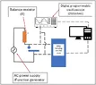
I am a mechanical engineer researching electrical damage in lubricated contacts. In my tests, I apply 18V DC across a steel ball-disc contact with an elastohydrodynamic lubrication film (more simply an oil film between 600-900 nanometers in thickness) between the surfaces. This film, according to recent research, acts as a capacitor and a resistor in parallel. I observe dielectric breakdown of the film (as expected, as the applied voltage exceeds the electric field strength of the film), and the voltage signal across the contact shows the breakdown as a voltage drop.

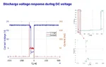
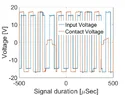
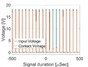
The voltage drops from 18V to 2V and has a duration between 80-100 microseconds. The current during the breakdown is limited to a maximum of 50 milliamperes using a variable resistor in series to the ball-disc contact. A sample signal of voltage and current captured during the test is attached, showing the nature of the breakdown. I also observe craters on the steel surfaces resembling the electric discharge damage.

Does the signal show an electric discharge or an arc? Because discharges are instantaneous and the signals show a standing wave in some cases, having a 100-microsecond duration. Also, if I want instantaneous discharge of energy and prevent arcing, is adding a capacitor in series the right way to move forward?

PAO50_U1000_1SRR_35T_18w_18V_50mA_Voltage_curren1.webp
 
Last edited by a moderator:
Engineering news on Phys.org
Welcome to PF.

AY156 said:
TL;DR: Electrical breakdown of oil film shows a signal resembling arcing. How do I prevent arcing to study electric discharge?

Does the signal show an electric discharge or an arc? Because discharges are instantaneous and the signals show a standing wave in some cases, having a 100-microsecond duration. Also, if I want instantaneous discharge of energy and prevent arcing, is adding a capacitor in series the right way to move forward?
The positive current spike at the instant of contact is the discharge of the electrode and cable capacitance. I see no oscillation that would be present if an arc was being maintained. I would expect an inductive voltage spike as the current stopped flowing.

A series capacitor would upset the DC bias voltage across the gap. It would require more than just a capacitor.

Are you aware of die sinking, or of wire EDM ?
https://en.wikipedia.org/wiki/Electrical_discharge_machining
EDM is carried out, submerged in a dielectric such as kerosene, that is used to flush debris from the deliberate spark erosion site.
You need the opposite response to the EDM contact break.
Any inductance will maintain an arc and keep it running by raising the instantaneous voltage when the current falls. You might minimise the inductance by using larger diameter hollow or cage conductors.

Place fast recovery diodes as close to the spark gap as possible. Connect one to ground, the other to a ceramic bypass capacitor on the 18 volt DC supply. That will keep the switching voltages low, preventing an arc.

Maybe there is a way to use a short transmission line to connect the test gap. That may eliminate the inductance if the line is sensibly terminated. The charge stored in the capacitance of the line will flow through the contact when it is made, but the voltage spike will be limited to twice the supply voltage. To prevent reflections, the line can be series terminated at the current limiting resistor.
 
Thank you for the response. Yes, I am very much aware of wire EDM and same kind of discharge damage is widely studied in lubricated contact in context of electrical damage in rolling-element bearings. Part of my research is to compare the damage in bearing to that observed in EDM. In my setup the wires are shielded and not long (maximum length 20 cm). Placing any component very close ton the contact is not possible since the contact is maintained inside a rig. It is important to note hear that the oil film is transient and dynamic and depends on the surface velocity, surface roughness among other things. DC is not a problem I have similar results with square wave AC voltage and I can use a capacitor with AC voltage to evaluate its effect.
 
To evaluate ways of preventing arcs, I am attempting a SPICE model of your test rig, but I need more information.
1. What is the diameter of the spherical ball that is one contact?
2. What is the diameter of the disc that makes the other contact?
3. Have you ever estimated or measured the contact capacitance?
4. Does the oil you use have a known dielectric constant, or should I guess it will be about 2.4 ?
5. I need details of the 20 cm connection to the contacts in the rig. Is it a twisted pair of wires in a screen? What dimensions? what specification?
6. Are details of the rig you use published and available online?
 
Baluncore said:
To evaluate ways of preventing arcs, I am attempting a SPICE model of your test rig, but I need more information.
1. What is the diameter of the spherical ball that is one contact?
2. What is the diameter of the disc that makes the other contact?
3. Have you ever estimated or measured the contact capacitance?
4. Does the oil you use have a known dielectric constant, or should I guess it will be about 2.4 ?
5. I need details of the 20 cm connection to the contacts in the rig. Is it a twisted pair of wires in a screen? What dimensions? what specification?
6. Are details of the rig you use published and available online?
Thank you for your help with this.
1. The ball diameter is 19.05 mm. But under the given test conditions, it forms a circular contact with the disc of radius approximately 104.334 microns.
2. Again, the disc diameter does not depend on the oil film. It is a ball on flat disc contact.
3. I have performed Electrochemical Impedance Spectroscopy to measure the Impedance of the contact and fit RC model to estimate the contact resistance and capacitance. It is in the order of hundreds of pico Farad.
4. The dielectric constant of the oil is measured to be 2.114.
5. I don't have details on the connections.
6. I can attach a schematic of the setup and some voltage signals captured during the DC voltage test, square wave AC voltage test at 10 kHz and DC pulse voltage DC (which is similar to EDM voltage).

I hope that helps.
 

Attachments

  • MTM-EC_AC.webp
    MTM-EC_AC.webp
    19.6 KB · Views: 1
  • PAO50_U1000_35T_1SRR_18w_18V_50mA_DC_signal.webp
    PAO50_U1000_35T_1SRR_18w_18V_50mA_DC_signal.webp
    24.3 KB · Views: 1
  • PAO50_U1000_1SRR_35T_18w_18V_50mA_10kHz_signal1.webp
    PAO50_U1000_1SRR_35T_18w_18V_50mA_10kHz_signal1.webp
    28.2 KB · Views: 1
  • PAO50_U1000_1SRR_35T_18w_18V_50mA_Pulse_10kHz_signal1.webp
    PAO50_U1000_1SRR_35T_18w_18V_50mA_Pulse_10kHz_signal1.webp
    25.9 KB · Views: 1
As I see it, you are experimenting with EDM die sinking, but you do not want it to actually remove metal, or for the die to sink.

There are two parts to each conduction event. Make, then break.

The first is the "make", or contact closure. At that moment, the gap capacitance is immediately discharged through the oil, without any possible external regulation of that high current discharge.
That capacitor energy, E = ½⋅C⋅V2; will heat and denature a small volume of oil, which may raise the temperature of the oil sufficiently, to erode the contacts. The capacitance is specified by the contact dimensions, so the only way to reduce erosion is to reduce the voltage. Lower voltage will break a thinner film of oil, so the capacitance will be proportionally greater, but the available energy will be reduced by the square. Going from 18 volts to 1 volt reduces energy by a factor of 182 = 324, but the thinner film capacitance rises by a factor of 18, so the energy reduction overall, is only by a factor of 18. I do not know how important it is for you to operate the rig at 18 volts, or with a 19 mm ball.

The second event is the "break", when the contacts open. The difference between your rig, and EDM is that, for EDM, series inductance would be used to maintain and repeat the arc, maximising arc energy, and so erosion. If you minimise inductance, say by using a snubber, or a terminated transmission line, then there is no reason to expect significant erosion during the single break event. It is the multiple re-strikes that causes the damage.

High current contacts are often plated with platinum, silver, tungsten or cadmium. The heavier metal reduces arc damage.

What if you plated the steel balls with an electrically resistive metal, or used carbon balls? Greater surface resistance will reduce the peak discharge current during the "make" event.

You might consider replacing the disc and steel ball with tungsten carbide material, WC. Is WC less susceptible to damage by arcing? WC bearing balls are an available commodity, while WC discs would need to be selected from a metal cutting tool manufacturer's stock.

1. Why 18 volts ?
2. Why the big 19.05mm = 3/4" ball ?
3. Why a steel ball ?
 
Thank you for the elaborate explanation. The mechanism is indeed similar to EDM, and is commonly observed in bearings on transmissions where currents are present. To understand the mechanism, this project uses a bearing steel ball (from an actual bearing). The 19.05mm ball is standard to be used with this rig. 18 V was selected to cause the discharges at the selected operating conditions.
So, I don't want to prevent the discharges or the damage associated with it, I am deliberately causing it to study it. What I want is to make sure the signals I'm acquiring are correct, and using the signals and observed damage, understand the physics behind it. Also, correlate the discharge energy calculated from the voltage signals and energy calculated based on the discharge craters observed on steel surfaces.
 
  • Like
Likes   Reactions: Baluncore

Similar threads

  • · Replies 27 ·
Replies
27
Views
3K
  • · Replies 5 ·
Replies
5
Views
3K