Discussion Overview
The discussion revolves around the use of electrical experiment boards, with participants exploring potential experiments and the identification of components on the boards. The scope includes practical experimentation and technical exploration of electronic components.
Discussion Character
- Exploratory, Technical explanation, Conceptual clarification
Main Points Raised
- One participant seeks assistance in conducting experiments with the electrical boards, expressing their inexperience.
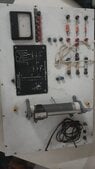
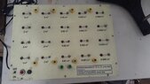
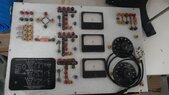
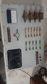
- Another participant comments on the boards being antique and questions the availability of documentation, suggesting a Google search for more information.
- A later reply mentions the association of the boards with Rajasthan University but notes the lack of additional information found.
- One participant suggests that the first experiment should involve investigating the components on the boards, including checking for damage and understanding their functions, such as current ratings and specifications.
- The same participant emphasizes that characterizing components is a common practice among electrical engineers, highlighting the importance of understanding how to use and identify parts.
Areas of Agreement / Disagreement
Participants generally agree on the need to investigate the components of the boards, but there is no consensus on specific experiments to conduct or the availability of documentation.
Contextual Notes
Some assumptions about the boards' components and their specifications remain unverified, and there is uncertainty regarding the completeness of available information.