Graphing Power vs Polarizer Angle using Intensity

In summary: P_{max}##.If you know ##P_{max}=1mW## then you can go one better and mark the y axis in mWs.In summary, The data collected from the experiment includes the polarizer angle measured in degrees, the recorded intensity measured in lux, the transmitted intensity measured in lux which is equal to the recorded lux minus the ambient lux, and the ambient lux. η = 0.543103 was also measured. There was confusion about finding the transmitted power of the laser, but the professor suggested using the values for intensity as they are directly proportional to power. The shape of the graph will be the same whether intensity or
  • #1
ChiralSuperfields
1,199
132
Homework Statement
Suppose you have a magnetic optical rail with a laser at one end and a lux meter at the other end. You place a polarizer in between. Find a graph of transmitted power ##P_{trans}## vs polarizer angle ##\theta##.

Given that efficiency of the polarizer is given by ##η = \frac{P_{trans}}{P_{max}} =\frac{I_{trans}}{I_{max}}## for when ##\theta = 0##, assume that ##η < 1##
Relevant Equations
Malus's law

##I_{trans} = I_{max}(\cos\theta)^2##
##\frac{P_{trans}}{A} = \frac{P_{max}}{A}(\cos\theta)^2## Since ##I = \frac{P}{A}##
##P_{trans} = P_{max}(\cos\theta)^2## (area can be cancelled since we are deriving this equation for one polarizer which we assume to have equal area on each side)
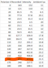
The data collected from the experiment is,
1677884483531.png

The first column is the polarizer angle measured in degrees.
The second column is recorded intensity measured in lux.
The third column is the transmitted intensity measured in lux. This is equal to the recorded lux - ambient lux
The fourth column is the ambient lux.

I also measured η = 0.543103 (dimensionless)

My confusion is how to find the transmitted power of the laser since the lux meter only reads the transmitted intensity.

So from the definition of power, should we multiply the transmitted intensity by the area of the polarizer? Or should we leave the transmitted power in terms of area A of the polarizer?

Many thanks!
 
Last edited:
Physics news on Phys.org
  • #2
Callumnc1 said:
how to find the transmitted power of the laser since the lux meter only reads the transmitted intensity.
You are not given any intensity or area, only ##P_{max}## and ##\eta##. So your y axis scale will only reference those.
 
  • Like
Likes ChiralSuperfields
  • #3
haruspex said:
You are not given any intensity or area, only ##P_{max}## and ##\eta##. So your y axis scale will only reference those.
Thank you for your reply @haruspex!

Sorry I have updated the post #1 to show my data collected.

Many thanks!
 
  • #4
Callumnc1 said:
Thank you for your reply @haruspex!

Sorry I have updated the post #1 to show my data collected.

Many thanks!
I don’t understand those numbers. How can you have a negative intensity? And how come the min and max are 180° apart instead of 90°?
 
  • Like
Likes ChiralSuperfields
  • #5
haruspex said:
I don’t understand those numbers. How can you have a negative intensity? And how come the min and max are 180° apart instead of 90°?
Thank you for your reply @haruspex!

Yeah I think we made a few mistakes in collecting that data for the second time. The intensity should not be negative. The light coming out of the laser is polarized however, we are were not too sure what the direction of linear polarization was.

I will find some other better data too analyze.

Many thanks!
 
  • #6
haruspex said:
I don’t understand those numbers. How can you have a negative intensity? And how come the min and max are 180° apart instead of 90°?
Sorry, it was actually me I did something some excel command.

Many thanks!
 
  • #7
Here is the new data @haruspex,

1677884092185.png

The first column is the polarizer angle measured in degrees.
The second column is recorded intensity measured in lux.
The third column is the transmitted intensity measured in lux. This is equal to the recorded lux - ambient lux
The fourth column is the ambient lux.

Many thanks!
 
  • #8
Callumnc1 said:
Here is the new data @haruspex,

View attachment 323168
The first column is polarizer angle measured in degrees.
The second column is record intensity measured in lux.
The third column is the transmitted intensity measured in lux. This is equal to the recorded lux - ambient lux
The fourth column is the ambient lux.

Many thanks!
That looks reasonable. But as you wrote, you can only graph intensity from that, unless you know the source power. Did you also collect the intensity without the filter?
 
  • Like
Likes ChiralSuperfields
  • #9
haruspex said:
That looks reasonable. But as you wrote, you can only graph intensity from that, unless you know the source power. Did you also collect the intensity without the filter?
Thank you for your reply @haruspex!

The power of the laser is 1 mW I think. Yes we did collect the intensity without the filter. The value read by the lux meter was 1136.7 lux.

Many thanks!
 
Last edited:
  • #10
haruspex said:
That looks reasonable. But as you wrote, you can only graph intensity from that, unless you know the source power. Did you also collect the intensity without the filter?
The professor at the labs said to get the graph of power vs polarizer angle, we could just use the values for intensity for power since they are directly proportional to each other (##I = \frac {P}{A}##)

However, I don't understand this explanation, is there a better way to explain this?

Many thanks!
 
  • #11
Callumnc1 said:
The professor at the labs said to get the graph of power vs polarizer angle, we could just use the values for intensity for power since they are directly proportional to each other (##I = \frac {P}{A}##)

However, I don't understand this explanation, is there a better way to explain this?

Many thanks!
The shape of the curve is the same whether intensity or power. The difference is what the y axis means in terms of dimensionality and units.
You could mark the y axis in terms of percentage of ##P_{max}##. You know ##I_{max}## (intensity with no filter). The measured intensity as a percentage of that is the same as the power as a percentage of ##P_{max}##.
If you know ##P_{max}=1mW## then you can go one better and mark the y axis in mWs.
 
  • Like
Likes ChiralSuperfields
  • #12
haruspex said:
The shape of the curve is the same whether intensity or power. The difference is what the y axis means in terms of dimensionality and units.
You could mark the y axis in terms of percentage of ##P_{max}##. You know ##I_{max}## (intensity with no filter). The measured intensity as a percentage of that is the same as the power as a percentage of ##P_{max}##.
If you know ##P_{max}=1mW## then you can go one better and mark the y axis in mWs.
Thank you for your reply @haruspex! That is very helpful!

Now that I have thought about it a bit more, I think I can see what you are saying.

So if we mark ##P_{max}## on the y-axis, then each value of the power below ##P_{max}##, that is, that transmitted power ##P_{trans}## will be some multiple ##n## of the max power where ##0 ≤ n < 1##. Therefore, each value of the transmitted power will be ##P(n)_{trans} = nP_{max}## where ##0 ≤ n < 1##.

To find ##n## we take the ratio of ##\frac{I_{trans}}{I_{max}}## (which is I derived by taking special cases of the intensity). So ##P_{trans} = \frac{I_{trans}P_{max}}{I_{max}}## where ##P_{max}## and ##I_{max}## are constants, and ##I_{trans}## is a function of the polarizer angle. That interesting because ##n## has a dimension of 1, so we do not need to worry about changing the units of lux.

So, I think if we were given the area of the polarizer then we would be able to graph power vs polarizer angle without knowing the max power. I don't think this it is possible to graph if we are not given the max power of the laser, would I please be correct?

Many thanks!
 
Last edited:
  • #13
Callumnc1 said:
if we were given the area of the polarizer then we would be able to graph power vs polarizer angle without knowing the max power. I don't think this it is possible to graph if we are not given the max power of the laser
Yes, you need either the max power or the area. Max power is better if you don't know how evenly the power is distributed over the area.
 
  • Like
Likes ChiralSuperfields
  • #14
haruspex said:
Yes, you need either the max power or the area. Max power is better if you don't know how evenly the power is distributed over the area.
Thank you for your help @haruspex! That is good to know!
 
  • #15
@haruspex do you please know how to calculate the polarization of the laser? For some reason I am getting a math error.

1678046283919.png

Also, I made a mistake is one of my posts, the column 1 is as I now realize is not actually the polarizer angle but the polarizer axis angle. The polarizer angle (##\theta##) is the relative angle between the plane of polarization of the laser (##\theta_l##) and the angle of the axis of the polarizer (##\theta_p##). ##\theta = \theta_l - \theta_p##

The values I am using to find the laser angle are ##I_{trans} = 152~lux## when ##\theta_p = 0## and ##I_{max} = 1160~lux##
##P_{max} = P_{trans}(\cos\theta)^2##
##P_{max} = \frac{152}{1160}P_{max}(\theta_l)^2##
##\cos^{-1} \sqrt{\frac{1160}{152}} = \theta_l##Many thanks!
 
Last edited:
  • #16
The max value for the transmitted intensity is when the polarizer axis is 160 degrees (seen graphically or from the table). So I think the plane of polarization of the laser is aligned with the polarizer axis at 160 degrees. Therefore, the laser angle must be 160 degrees. However, I am interesting how find it is using Malus' law.

Many thanks!
 
  • #17
Callumnc1 said:
The values I am using to find the laser angle are ##I_{trans} = 152~lux## when ##\theta_p = 0## and ##I_{max} = 1160~lux##
Surely you want the minimum and maximum intensities (after subtracting ambient), which occur around 40°-50° and 130°-140° 50-60° and 140-150° in your table. Reassuringly, those are 90° apart.
Ideally, you should do a least squares fit to pin this down more accurately, but it looks to me that the true minimum would be around 52-54° and max at 142-144°.

Having determined that, it gives you an adjustment angle to move the minimum to 90° and the max to 0° (modulo 180°).
Callumnc1 said:
##P_{max} = P_{trans}(\cos\theta)^2##
Check that equation. It would make the transmitted power more than the maximum at most angles.
 
Last edited:
  • Like
Likes ChiralSuperfields
  • #18
Thank you very much for you reply @haruspex!
haruspex said:
Surely you want the minimum and maximum intensities (after subtracting ambient), which occur around 40°-50° and 130°-140° in your table. Reassuringly, those are 90° apart.
Ideally, you should do a least squares fit to pin this down more accurately, but it looks to me that the true minimum would be around 52-54° and max at 142-144°.
I thought Malus' law would work for any value from the table substituted into the equation.

Why is the max intensity at 130°-140° (or 142-144°) not 160°? I understand what you mean when you say that max and min laser angles should be separated by 90°. I find that the min intensity to be at 50° however, and this is 110° from the max intensity (which I found from the table to be at 160°).

1678051195283.png


haruspex said:
Having determined that, it gives you an adjustment angle to move the minimum to 90° and the max to 0° (modulo 180°).

Check that equation. It would make the transmitted power more than the maximum at most angles.
Do you mean change the plane of polarization of the laser by rotating it?

Many thanks!
 

Attachments

  • 1678050728072.png
    1678050728072.png
    15.4 KB · Views: 48
  • #19
haruspex said:
Surely you want the minimum and maximum intensities (after subtracting ambient), which occur around 40°-50° and 130°-140° in your table. Reassuringly, those are 90° apart.
Ideally, you should do a least squares fit to pin this down more accurately, but it looks to me that the true minimum would be around 52-54° and max at 142-144°.

Having determined that, it gives you an adjustment angle to move the minimum to 90° and the max to 0° (modulo 180°).

Check that equation. It would make the transmitted power more than the maximum at most angles.
Sorry @haruspex I see what you mean about the equation. I will fix that.

Many thanks!
 
  • #20
Sorry, I made a few mistakes there. Please see the edited version.
The 160° reading looks like an outlier. If you graph the data you have this should be evident. But I'll try to figure out a way to do a proper regression fit.
 
  • Like
Likes ChiralSuperfields
  • #21
haruspex said:
Sorry, I made a few mistakes there. Please see the edited version.
The 160° reading looks like an outlier. If you graph the data you have this should be evident. But I'll try to figure out a way to do a proper regression fit.
Thank you for your reply @haruspex!

Please don't worry about your mistakes! I have graphed it on excel. I see what you mean that 160 degrees is a outlier. Maybe I should try an extrapolate to find the max?

Many thanks!
 
Last edited:
  • #22
Hi @haruspex,

Thank you for pointing out my mistake with the equation. I have below tried with correct equation, however, there seems to be massive discrepancy when I use values.

##P_{trans} = P_{max}(\cos\theta)^2##
##\frac{152}{1160}P_{max} = P_{max}(\cos\theta_l)^2##
##\cos^{-1} \sqrt{\frac{152}{1160}} = \theta_l##
## 69~degrees = \theta_l## which dose not seem to correct. I think it will be more accurate if done graphically since we take into account more data.

If the axis of the polarizer is 150 degrees where the transmitted intensity is 408.8 lux then,

##P_{trans} = P_{max}(\cos\theta)^2##
##\frac{408.8}{1160}P_{max} = P_{max}(\cos[\theta_l - 150])^2## where ##\theta_p = 150##
##\cos^{-1} \sqrt{\frac{404.8}{1160}} + 150 = \theta_l##
##204~degrees = \theta_l##

Would you please know why?

Many thanks!
 
  • #23
Callumnc1 said:
Hi @haruspex,

Thank you for pointing out my mistake with the equation. I have below tried with correct equation, however, there seems to be massive discrepancy when I use values.

##P_{trans} = P_{max}(\cos\theta)^2##
##\frac{152}{1160}P_{max} = P_{max}(\cos\theta_l)^2##
##\cos^{-1} \sqrt{\frac{152}{1160}} = \theta_l##
## 69~degrees = \theta_l## which dose not seem to correct. I think it will be more accurate if done graphically since we take into account more data.

If the axis of the polarizer is 150 degrees where the transmitted intensity is 408.8 lux then,

##P_{trans} = P_{max}(\cos\theta)^2##
##\frac{408.8}{1160}P_{max} = P_{max}(\cos[\theta_l - 150])^2## where ##\theta_p = 150##
##\cos^{-1} \sqrt{\frac{404.8}{1160}} + 150 = \theta_l##
##204~degrees = \theta_l##

Would you please know why?

Many thanks!
Where does 1160 come from? You quoted 1137 for the lux without the filter.

But I just realised your Relevant Equations are confusing two things:
Callumnc1 said:
Given that efficiency of the polarizer is given by ##η = \frac{P_{trans}}{P_{max}} =\frac{I_{trans}}{I_{max}}## for when ##\theta = 0##, assume that ##η < 1##
Relevant Equations:: Malus's law

##I_{trans} = I_{max}(\cos\theta)^2##
##\frac{P_{trans}}{A} = \frac{P_{max}}{A}(\cos\theta)^2##
In ##η = \frac{P_{trans}}{P_{max}} =\frac{I_{trans}}{I_{max}}##, ##P_{trans}## is the lux with the filter at 0° and ##P_{max}## is the lux without the filter.
In ##{P_{trans}} = {P_{max}}(\cos\theta)^2## , ##P_{trans}## is the lux with the filter at angle ##\theta## and ##P_{max}## is the lux with the filter at 0°.

It might help if we change the notation a bit:
##η = \frac{P_{0°}}{P_{source}}##
##{P_{\theta}} = {P_{0°}}(\cos\theta)^2##.
Combining them: ##{P_{\theta}} =\eta {P_{source}}(\cos\theta)^2##.
 
  • Like
Likes ChiralSuperfields
  • #24
haruspex said:
Where does 1160 come from? You quoted 1137 for the lux without the filter.
Thank you for your reply @haruspex!

Sorry I forgot to subtract the ambient lux from 1160 so 1137 is the correct value. I am thinking about you next paragraphs.

Many thanks!
 
  • #25
haruspex said:
But I just realised your Relevant Equations are confusing two things:

In ##η = \frac{P_{trans}}{P_{max}} =\frac{I_{trans}}{I_{max}}##, ##P_{trans}## is the lux with the filter at 0° and ##P_{max}## is the lux without the filter.
In ##{P_{trans}} = {P_{max}}(\cos\theta)^2## , ##P_{trans}## is the lux with the filter at angle ##\theta## and ##P_{max}## is the lux with the filter at 0°.

It might help if we change the notation a bit:
##η = \frac{P_{0°}}{P_{source}}##
##{P_{\theta}} = {P_{0°}}(\cos\theta)^2##.
Combining them: ##{P_{\theta}} =\eta {P_{source}}(\cos\theta)^2##.
Thank you for your reply @haruspex!

Sorry, did you mean that

In ##η = \frac{P_{trans}}{P_{max}} =\frac{I_{trans}}{I_{max}}##, ##P_{trans}## is the power with the filter at 0° and ##P_{max}## is the power without the filter.
In ##{P_{trans}} = {P_{max}}(\cos\theta)^2## , ##P_{trans}## is the power with the filter at angle ##\theta## and ##P_{max}## is the power with the filter at 0°.

?

I am not sure whether the slanted bit is correct. In ##{P_{trans}} = {P_{max}}(\cos\theta)^2## , ##P_{trans}## is the power with the filter at angle ##\theta## and ##P_{max}## is the power with the filter at 0°. According to the textbook screen shot below, ##I_{max}## (or ##P_{max}##) is the power of the polarized beam before going though polarizer (i.e it the power without the filter).

Do you please know weather that is correct?

1678062024427.png

Where ##I_0 = I_{max} = P_{max}##

The screen shot was taken from https://openstax.org/books/university-physics-volume-3/pages/1-7-polarization

Many thanks!
 
Last edited:
  • #26
Callumnc1 said:
did you mean that

In ##η = \frac{P_{trans}}{P_{max}} =\frac{I_{trans}}{I_{max}}##, ##P_{trans}## is the power with the filter at 0° and ##P_{max}## is the power without the filter.
In ##{P_{trans}} = {P_{max}}(\cos\theta)^2## , ##P_{trans}## is the power with the filter at angle ##\theta## and ##P_{max}## is the power with the filter at 0°
Yes, that’s what I meant.
Callumnc1 said:
I am not sure whether the slanted bit is correct. In ##{P_{trans}} = {P_{max}}(\cos\theta)^2## , ##P_{trans}## is the power with the filter at angle ##\theta## and ##P_{max}## is the power with the filter at 0°. According to the textbook screen shot below, ##I_{max}## (or ##P_{max}##) is the power of the polarized beam before going though polarizer (i.e it the power without the filter).
If the filter is perfect, it comes to the same. With the filter at 0° to the existing polarisation, all the light passes through: ##P_{\theta=0}=P_{source}##.
More generally, some light is lost: ##P_{\theta=0}=\eta P_{source}##.
 
  • Like
Likes ChiralSuperfields
  • #27
haruspex said:
Yes, that’s what I meant.

If the filter is perfect, it comes to the same. With the filter at 0° to the existing polarisation, all the light passes through: ##P_{\theta=0}=P_{source}##.
More generally, some light is lost: ##P_{\theta=0}=\eta P_{source}##.
Thank you for your reply @haruspex!

I'm going to try do some more thinking to see why this is true.

Many thanks!
 
  • #28
Did some thinking about fitting to the data.
You have a set of datapoints (xi, yi), being columns A, C. The x values are equally spaced over a range of 180°. That's helpful.
The problem is equivalent to fitting the curve ##y=A\sin(2x+\phi)+B## to the data. A very good estimate for B would be the average of the yi, so we can write ##Y_i=y_i-\bar y_i## and ##Y=A\sin(2x+\phi)##.
It turns out that to minimise the least squares error, ##\tan(\phi)=\frac{\Sigma_i Y_i\cos(2x_i)}{\Sigma_i Y_i\sin(2x_i)}##. (This would be a lot messier with an arbitrary set of x values.)
Having found ##\phi##, the value of A that minimises the sum of squares is ##\frac{\Sigma_i Y_i\sin(2x_i+\phi)}{\Sigma_i\sin^2(2x_i+\phi)}##.

Are you able to carry those calculations through? If not, please post your data in a form in which I can paste it into a spreadsheet.
 
  • Like
Likes ChiralSuperfields
  • #29
haruspex said:
Did some thinking about fitting to the data.
You have a set of datapoints (xi, yi), being columns A, C. The x values are equally spaced over a range of 180°. That's helpful.
The problem is equivalent to fitting the curve ##y=A\sin(2x+\phi)+B## to the data. A very good estimate for B would be the average of the yi, so we can write ##Y_i=y_i-\bar y_i## and ##Y=A\sin(2x+\phi)##.
It turns out that to minimise the least squares error, ##\tan(\phi)=\frac{\Sigma_i Y_i\cos(2x_i)}{\Sigma_i Y_i\sin(2x_i)}##. (This would be a lot messier with an arbitrary set of x values.)
Having found ##\phi##, the value of A that minimises the sum of squares is ##\frac{\Sigma_i Y_i\sin(2x_i+\phi)}{\Sigma_i\sin^2(2x_i+\phi)}##.

Are you able to carry those calculations through? If not, please post your data in a form in which I can paste it into a spreadsheet.
Thank you for your reply @haruspex!

Please don't worry about doing those calculations. I am not familiar with fitting data, but they are teaching basic linear regression this week, so I don't think they expect that used yet. I think they were just looking for us to find the approximate laser angle from where the polarizer axis angle has the largest transmitted intensity.

The data collected is below if you are interested.

Many thanks!

Polarizer axis angleRecorded Intensity (Lux)Intensity (Lux)Ambient Intensity (Lux)
0​
163​
152​
11​
10​
121​
110​
11​
20​
81.5​
75​
6.5​
30​
77.9​
57.8​
20.1​
40​
23.5​
11.3​
12.2​
50​
23.5​
3.5​
20​
60​
23.1​
4.1​
19​
70​
23.5​
11.5​
12​
80​
50.5​
40.5​
10​
90​
127.7​
109.9​
17.8​
100​
162.5​
148​
14.5​
110​
212​
201.2​
10.8​
120​
316​
299.9​
16.1​
130​
347​
327.9​
19.1​
140​
436​
412.8​
23.2​
150​
432​
408.8​
23.2​
160​
455​
433.5​
21.5​
170​
240​
227.5​
12.5​
180​
199​
188.1​
10.9​
p.s. Feel free to remind me if I forget to like your replies
 
Last edited:
  • #30
haruspex said:
Yes, that’s what I meant.

If the filter is perfect, it comes to the same. With the filter at 0° to the existing polarisation, all the light passes through: ##P_{\theta=0}=P_{source}##.
More generally, some light is lost: ##P_{\theta=0}=\eta P_{source}##.
Thank you very much for pointing that out @haruspex!

It appears there must be an error in that textbook I was using. I checked HRK vol 2 and found
1678091861411.png

Which agrees with what you said.

Many thanks!
 
  • #31
Oh wait, I think the OpenStax textbook just assumed an efficiency equal to 1.

Many thanks!
 
  • #32
I plotted your data. Normally, one assumes the x values are reliable, so curve fitting minimises the sum of squares of the errors in y, but your data looks very odd. The trough on the left is about 112° wide, then the crest is only 68° wide. It's as though there is some systematic error in the angle readings.
Alternatively, the high crest on the right is what's wrong. If we throw away the data from 120° to 170° then the curve looks respectable. Sketching in the gap created, the peak would only be about 130.

I assume you only did one run-through of the settings, which is a shame.

Anyway, I was able to verify my formulae.
 
  • Like
Likes ChiralSuperfields
  • #33
haruspex said:
I plotted your data. Normally, one assumes the x values are reliable, so curve fitting minimises the sum of squares of the errors in y, but your data looks very odd. The trough on the left is about 112° wide, then the crest is only 68° wide. It's as though there is some systematic error in the angle readings.
Alternatively, the high crest on the right is what's wrong. If we throw away the data from 120° to 170° then the curve looks respectable. Sketching in the gap created, the peak would only be about 130.

I assume you only did one run-through of the settings, which is a shame.

Anyway, I was able to verify my formulae.
Thank you for doing that @haruspex!

Many thanks!
 

1. What is the purpose of graphing power vs polarizer angle using intensity?

The purpose of this type of graph is to visually represent the relationship between power and polarizer angle using intensity as a measure. This can help scientists understand how different angles of the polarizer affect the intensity of the light passing through it.

2. How is intensity measured in this type of graph?

Intensity is typically measured in units of power per unit area, such as watts per square meter (W/m2). This can be measured using a light meter or other specialized equipment.

3. What does the slope of the graph represent?

The slope of the graph represents the change in intensity per unit change in polarizer angle. A steeper slope indicates a larger change in intensity for a given change in angle, while a flatter slope indicates a smaller change in intensity.

4. How does the intensity change as the polarizer angle increases?

The intensity typically decreases as the polarizer angle increases, as more light is blocked by the polarizer at larger angles. This relationship can be seen in the downward trend of the graph.

5. What other factors can affect the relationship between power and polarizer angle?

Other factors that can affect this relationship include the type of light source, the quality of the polarizer, and any external factors that may affect the intensity of the light, such as reflections or obstructions in the path of the light.

Similar threads

  • Other Physics Topics
Replies
2
Views
3K
  • Introductory Physics Homework Help
Replies
10
Views
2K
  • Introductory Physics Homework Help
Replies
6
Views
813
  • Introductory Physics Homework Help
Replies
24
Views
1K
Replies
2
Views
3K
Replies
17
Views
3K
Replies
6
Views
2K
  • Introductory Physics Homework Help
Replies
1
Views
1K
  • Introductory Physics Homework Help
Replies
11
Views
2K
  • Introductory Physics Homework Help
Replies
1
Views
2K
Back
Top