Having issues series resistive and reactive impedance matching

  • Engineering
  • Thread starter mechorigin
  • Start date
  • #1
mechorigin
2
0
Homework Statement:
Having issues with getting the same series resistive and reactive impedance of the coil and cap they did in the figures
Relevant Equations:
reactance equations, angular frequency, and Q
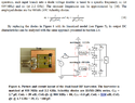
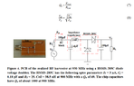
The only thing I could think of was using Q=sqrt(6000/50)-1 = 10.9, which then gets me XL=545 and XC=550, or 96.4nH, and 0.32pF at resonance of 900Mhz. I tried seeing if Zin=Zout equation would bring me close, so I tried Z=545+(50-550)=45, then XL for 38.5nH was 217.7, and XC for 2.4pF was 74. Of course Z=217+(50-74) equals 193. so 45 does not equal 193. but then I realized there was an absorption method for the stray capacitance inherent in the diodes. totaling roughly 0.36pF for 0.18pF each diode. So from here I tried calculating the two capacitance I had as if they were in parallel, giving me around 0.68pF total. With an XL of 220, and XC of 260 I tried Z=220+(50-260)=10. Closer, but not quite. The full research paper I am referencing doing my homework on: https://www.aimspress.com/article/id/274
 

Attachments

  • 1.PNG
    1.PNG
    62.8 KB · Views: 49
  • 2.PNG
    2.PNG
    20.4 KB · Views: 48

Answers and Replies

  • #2
tech99
Science Advisor
Gold Member
2,643
1,187
I think the antenna is a quarter wave vertical, presumably 50 Ohms, although I cannot see the impedance of the antenna stated. But I notice that the matching network shown, which is an L-match, is configured to produce a step down in impedance to the diodes rather than the required step up.
 
  • #3
tech99
Science Advisor
Gold Member
2,643
1,187
I also tend to think that it might be better to add the signals at RF rather than at DC. Adding the signals at RF gives a higher RF peak voltage.
 
  • #4
mechorigin
2
0
Interesting, I could give that a try, although I will have to dig through my textbooks, I forgot how to add the signals at RF cause I usually do it at DC. Though I've never had to analyze something this complex before.

Yeah I would presume it was at 50 ohms as well, as well as the paper suggests it to be used with (~λ/4 at 900 MHz, and 2200?) and because the diodes have such a low forward voltage and the junction capacitance is roughly 0.18pF each, I would assume the matching circuit might have to match down as to not add more components due to parasitic effects.

Still having issues with getting the same results they did, especially in the dual-band RF harvester circuit.
 

Suggested for: Having issues series resistive and reactive impedance matching

  • Last Post
Replies
2
Views
407
Engineering Finding the Impedance
  • Last Post
Replies
3
Views
612
  • Last Post
Replies
2
Views
294
  • Last Post
Replies
1
Views
300
Replies
29
Views
4K
  • Last Post
Replies
12
Views
965
Replies
2
Views
1K
Replies
20
Views
2K
  • Last Post
Replies
1
Views
1K
Top