erobz said:
Thanks!
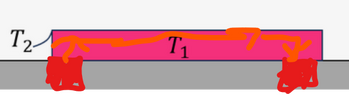
No, They are different. ##T_1## is the ss temp of the strip. We neglect thermal gradients in this body because its a relatively thin metallic substance with a high thermal conductivity. We assume that everywhere in the strip is uniformly ##T_1##. There must be a temperature differential for heat to be transferred. Hence the surrounding air ( just outside of the convection boundary layer between it and the conductor ) in the box is ##T_2##.
Its more accounting.
It's about the boundary area. Imagine it is a thin film, heat is transferred across it, and in the direction of flow. We ignore this last part, that's why ##h## changes along the length. We are hand waiving that away. As for the open duct, the flow entering/exiting does not have a convection boundary with itself...it requires relative motion.
As for the green area, whatever you want to do with it. In the case of a solid conductor the flow which carries heat away would hit it...relative motion. BUT its a pretty tiny area, its most likely not worth the trouble of factoring it in unless you want to keep options open for geometry changes.
Note: You may have to scroll to the right to see the full post.
Thanks! I think it's getting a bit to complicated, with to many unknown variables, it will not be possible to calculate a current. I will try to represent this problem statement, with a current that can actually be found, along with simplifications, and why they can be made. If any of the simplifications are not required, please let me know.
Problem Statement
Evaluate the ampacity of an uninsulated nickel strip that is 0.1 mm thick ##t_{S}##, 10 mm wide ##W##, and 63 mm long ##L##. Additional details are intentionally not provided. This in alignment with current ratings of commercial cables that do not specify ambient air conditions, if the cable is within a container, or if additional insulation is placed around the cable. The orientation of the nickel strip is also not specified. Assume that it can be used in any orientation in outdoor conditions.
Assessment of ambient air conditions
We will take the liberty of assuming that the conductor will not be used in ambient temperature ##T_{\infty}## conditions greater than ##100\;deg\;F##. This is a reasonable maximum temperature for most areas on the planet. There are certainly places that do not get this hot or places that get even hotter. However, because the current is dependent on the difference between the temperature of the strip ##T_{S}## and ##T_{\infty}##, for safety reasons it is best to assume that ##T_{\infty}## is as large as possible for a variety of areas.
$$T_{\infty} = (100\;deg\;F - 32)\frac{5}{9} = 37\;\frac{7}{9}\;deg\;C$$
$$(37\;\frac{7}{9}\;deg\;C+273.15)\frac{K}{C}\;is\;about\;310.928\;K$$
Assessment of temperature of the strip
Nickel strips are typically used in the assembly of battery packs. Most cells have a maximum operating temperature of ##T_{S} = 60\;deg\;C##. While this puts us at the absolute maximum temperature, it will become clear later on in this problem that the actual current we find is an underestimate, so being right at the boundary condition is acceptable.
$$(60\;deg\;C+273.15)\frac{K}{C} = 333.15\;K$$
$$\dot{Q} = Q_{1} + Q_{2} + Q_{3}...$$
Where:
##\dot{Q}## is the total heat transferred.
##Q_{n}## is a the nth heat transfer.
$$P = I_{A}^{2}\;R$$
Where:
##P## is the power created by sending current through the strip.
##I_{A}^{2}## is the ampacity current.
##R## is the resistance of the strip.
$$R = \frac{\rho\;L}{A} = \frac{\rho\;L}{Wt_{S}}$$
Where:
##\rho## is the resistivity of the material, for nickel it's ##6.99 * 10^{-8} \Omega\;m##
##L## is the length of the strip, parallel to the flow of current
##A## is the surface area perpendicular to the flow of current
##W## W is the width of the strip, perpendicular to the flow of current
##t_{S}## is the thickness of the strip, perpendicular to the flow of current
$$P = I_{A}^{2}\;R = I_{A}^{2}\;\frac{\rho\;L}{Wt_{S}}$$
$$I_{A}^{2}\;\frac{\rho\;L}{Wt_{S}} = Q_{1} + Q_{2} + Q_{3}...$$
$$I_{A}^{2} = \frac{Wt_{S}}{\rho\;L}(Q_{1} + Q_{2} + Q_{3}...)$$
$$I_{A} = \sqrt{\frac{Wt_{S}}{\rho\;L}(Q_{1} + Q_{2} + Q_{3}...)}$$
Kapton Tape Insulation Thermal Specifications:
Thermal conductivity ##k = 0.12 \frac{W}{m\;K}##.
Thickness ##t_{I} = 0.03 mm##
Lithium Ion Cell Thermal Specifications:
Thermal conductivity ##k = Unknown##
Thickness of 21700 cell ##t = 70 mm##
Thickness of 18650 cell ##t = 65 mm##
Heat Transfer via Convection:
$$Q =(T_{S} - T_{\infty})\sum_{n = 1}^{n} h_n*A_n$$
Where:
##h_{n}## is the heat transfer coefficient of nth surface area.
##A_{n}## is the nth surface area.
##T_{1}## is the temperature of the hotter object
##T_{2}## is the temperature of the colder object
Heat Transfer via Conduction
$$Q = \frac{kA(T_{1} - T_{2})}{t}$$
Where:
##t## is the thickness of the material that heat is being transferred to.
There are many heat transfers that take place, and many temperatures that are unknown and cannot be calculated based on the six known variables ##L\;W\;t\;T_{\infty}\;T_{S}\;\rho##
$$\sqrt{\frac{Wt}{\rho\;L}(Q_{1} + Q_{2} + Q_{3}...)} > \sqrt{\frac{Wt}{\rho\;L}Q_{1}}$$
Hence if we consider only convection of the strip in ambient temperature conditions T_{\infty}, it will produce a current value smaller than the actual value if we were to consider:
- Heat transfer via conduction from the temperature difference between the cells and the strip
- Heat transfer via conduction from the strip to the insulation from the temperature difference between the strip and the insulation
- Heat transfer via radiation from the temperature difference between the insulation and other electrical components within the box
- Heat transfer via convection from the temperature difference between the insulation and the air within the box
- Heat transfer via convection from the temperature difference between the air in the box and the air outside of the box
- Likely others that I'm forgetting...
We will consider the temperature of the cells, the temperature of the insulation, the temperature of the air within the box, all to be the same temperature as the strip. Hence, we will consider heat transfer via convection from the strip and the ambient air conditions.
Assessment of Surface Areas Exposed to Ambient Air Conditions
In order to provide the best estimation of the current, we will assume that the "bottom" of the strip is resting on some other surface, but we will not consider the heat transfer via conduction from the strip and this other material. Meaning that the strip is not "floating". Additionally we will assume that the other five surfaces of the strip are exposed to ambient air conditions. This is a reasonable assessment to make, considering that nickel strips are typically spot welded to cells (the thing that the strip is resting on). We will also assume that each surface area is at the same temperature. Meaning that each surface area is at ##T_{S}##.
$$\dot{Q} =(T_{S} - T_{\infty})\sum_{n=1}^{5} h_n*A_n$$
$$A = LW + Wt + Wt + Lt + Lt = LW + 2Wt + 2Lt$$
$$\dot{Q} =(T_{S} - T_{\infty})(h_{LW}LW + 2h_{Wt}Wt + 2h_{Lt}Lt)$$
$$I_{A} = \sqrt{\frac{Wt}{\rho\;L}(T_{S} - T_{\infty})(h_{LW}LW + 2h_{Wt}Wt + 2h_{Lt}Lt)}$$
$$h_{n_{HV}} = \frac{k N_{n_{HV}}}{L_{C_{n_{HV}}}}$$
Where:
##h_{n_{HV}}## is the heat transfer coefficient of surface area ##n## in either the horizontal ##H##, Vertical ##V## orientation
##N_{n_{HV}}## is Nusselt Number surface area ##n## in either the horizontal ##H##, Vertical ##V## orientation
##L_{C_{n_{HV}}}## is the characteristic length of surface area ##n## in either the horizontal ##H##, Vertical ##V## orientation
$$I_{A} = \sqrt{\frac{kWt}{\rho\;L}} \sqrt{T_{S} - T_{\infty}} \sqrt{\frac{N_{LW_{HV}}}{L_{C_{LW_{HV}}}}LW + 2\frac{N_{Wt_{HV}}}{L_{C_{Wt_{HV}}}}Wt + 2\frac{N_{Lt_{HV}}}{L_{C_{Lt_{HV}}}}Lt}$$
There are three possible orientations that must be considered
| Option | LW | Wt | Lt |
1 | H | V | V |
2 | V | H | V |
3 | V | V | H |
Characteristic Lengths
For Horizontal surfaces, it's the surface area divided by the perimeter
For Vertical or Inclined surfaces, it's the vertical height
$$L_{C_{LW_{H}}} = \frac{LW}{2L+2W}$$
$$L_{C_{LW_{V}}} = L\;or\;W$$
$$L_{C_{Wt_{H}}} = \frac{Wt}{2W+2t}$$
$$L_{C_{Wt_{V}}} = W\;or\;t$$
$$L_{C_{Lt_{H}}} = \frac{Lt}{2L+2t}$$
$$L_{C_{Lt_{V}}} = L\;or\;t$$
| Option | LW | Wt | Lt |
1 | H, L_C = LW/(2(L+W)) | V, L_C = t | V, L_C = t |
2 | V, L_C = L | H, L_C = Wt/(2(W+t)) | V, L_C = L |
3 | V, L_C = W | V, L_C = t | H, L_C = Lt/(2(L+t)) |
$$I_{A} = \sqrt{\frac{kWt}{\rho\;L}} \sqrt{T_{S} - T_{\infty}} \sqrt{\frac{N_{LW_{HV}}}{L_{C_{LW_{HV}}}}LW + 2\frac{N_{Wt_{HV}}}{L_{C_{Wt_{HV}}}}Wt + 2\frac{N_{Lt_{HV}}}{L_{C_{Lt_{HV}}}}Lt}$$
Option 1
$$I_{A} = \sqrt{\frac{kWt}{\rho\;L}} \sqrt{T_{S} - T_{\infty}} \sqrt{\frac{N_{LW_{H}}}{L_{C_{LW_{H}}}}LW + 2\frac{?_{Wt_{V}}}{L_{C_{Wt_{V}}}}Wt + 2\frac{?_{Lt_{V}}}{L_{C_{Lt_{V}}}}Lt}$$
$$I_{A} = \sqrt{\frac{kWt}{\rho\;L}} \sqrt{T_{S} - T_{\infty}} \sqrt{\frac{N_{LW_{H}}}{\frac{LW}{2(L+W)}}LW + 2\frac{N_{Wt_{V}}}{t}Wt + 2\frac{?_{Lt_{V}}}{t}Lt}$$
$$I_{A} = \sqrt{\frac{kWt}{\rho\;L}} \sqrt{T_{S} - T_{\infty}} \sqrt{2(L+W)N_{LW_{H}} + 2WN_{Wt_{V}}+ 2L?_{Lt_{V}}}$$
$$I_{A} = \sqrt{\frac{2kWt}{\rho\;L}} \sqrt{T_{S} - T_{\infty}} \sqrt{(L+W)N_{LW_{H}} + WN_{Wt_{V}}+ LN_{Lt_{V}}}$$
Option 2
$$I_{A} = \sqrt{\frac{kWt}{\rho\;L}} \sqrt{T_{S} - T_{\infty}} \sqrt{\frac{N_{LW_{V}}}{L_{C_{LW_{V}}}}LW + 2\frac{N_{Wt_{H}}}{L_{C_{Wt_{H}}}}Wt + 2\frac{N_{Lt_{V}}}{L_{C_{Lt_{V}}}}Lt}$$
$$I_{A} = \sqrt{\frac{kWt}{\rho\;L}} \sqrt{T_{S} - T_{\infty}} \sqrt{\frac{N_{LW_{V}}}{L}LW + 2\frac{N_{Wt_{H}}}{\frac{Wt}{2(W+t)}}Wt + 2\frac{N_{Lt_{V}}}{L}Lt}$$
$$I_{A} = \sqrt{\frac{kWt}{\rho\;L}} \sqrt{T_{S} - T_{\infty}} \sqrt{WN_{LW_{V}} + 2*2(W+t)N_{Wt_{H}} + 2tN_{Lt_{V}}}$$
$$I_{A} = \sqrt{\frac{kWt}{\rho\;L}} \sqrt{T_{S} - T_{\infty}} \sqrt{WN_{LW_{V}} + 4(W+t)?_{Wt_{H}} + 2tN_{Lt_{V}}}$$
Option 3
$$I_{A} = \sqrt{\frac{kWt}{\rho\;L}} \sqrt{T_{S} - T_{\infty}} \sqrt{\frac{N_{LW_{V}}}{L_{C_{LW_{V}}}}LW + 2\frac{N_{Wt_{V}}}{L_{C_{Wt_{V}}}}Wt + 2\frac{N_{Lt_{H}}}{L_{C_{Lt_{H}}}}Lt}$$
$$I_{A} = \sqrt{\frac{kWt}{\rho\;L}} \sqrt{T_{S} - T_{\infty}} \sqrt{\frac{N_{LW_{V}}}{W}LW + 2\frac{N_{Wt_{V}}}{t}Wt + 2\frac{N_{Lt_{H}}}{\frac{Lt}{2(L+t)}}Lt}$$
$$I_{A} = \sqrt{\frac{kWt}{\rho\;L}} \sqrt{T_{S} - T_{\infty}} \sqrt{LN_{LW_{V}} + 2WN_{Wt_{V}} + 2*2(L+t)N_{Lt_{H}}}$$
$$I_{A} = \sqrt{\frac{kWt}{\rho\;L}} \sqrt{T_{S} - T_{\infty}} \sqrt{LN_{LW_{V}} + 2WN_{Wt_{V}} + 4(L+t)N_{Lt_{H}}}$$
Rayleigh number
$$Ra_{L_{C}} = \frac{g\beta (T_{S} - T_{\infty})L_{C}^{3}}{v \alpha}$$
Where:
##Ra_{L_{C}}## is the Rayleigh number of characteristic length ##L_{C}##
##g## is the acceleration due to gravity, ##9.81456 \frac{m}{s^{2}}##.
##\beta## is the expansion coefficient in ##\frac{1}{K}##, ##\beta = \frac{1}{T_{\infty}} = \frac{1}{333.15}\;\frac{1}{K}##
##v## is the kinematic viscosity in ##\frac{m^{2}}{s}##, ##v =(-0.000000000000022928 \frac{m^{2}}{s\;K^{3}})T_{\infty}^{3} + (0.00000000011574 \frac{m^{2}}{s\;K^{2}})T_{\infty}^2 + (0.000000028239 \frac{m^{2}}{s\;K})T_{\infty} - (0.0000024125 \frac{m^{2}}{s}) =(-0.000000000000022928 \frac{m^{2}}{s\;K^{3}})*(310.928\;K)^{3} + (0.00000000011574 \frac{m^{2}}{s\;K^{2}})*(310.928\;K)^2 + (0.000000028239 \frac{m^{2}}{s\;K})*(310.928\;K) - (0.0000024125 \frac{m^{2}}{s})\;is\;about\;1.68679*10^{-5} \frac{m^{2}}{s}##
##\alpha## is the thermal diffusivity in ##\frac{m^{2}}{s}##, ##\alpha = (-0.000000000000052324)T_{\infty}^{3} + (0.00000000018976)T_{\infty}^{2} + (0.0000000339)T_{\infty} - (0.000003888) = (-0.000000000000052324)(310.928\;K)^{3} + (0.00000000018976)(310.928\;K)^{2} + (0.0000000339)(310.928\;K) - (0.000003888)\;is\;about\;2.34249*10^{-5} \frac{m^{2}}{s}##
$$Ra_{L_{C}} = \frac{(9.81456 \frac{m}{s^{2}})(\frac{1}{333.15}\;\frac{1}{K}) (333.15 K - 310.928 K)}{(1.68679*10^{-5} \frac{m^{2}}{s}) (2.34249*10^{-5} \frac{m^{2}}{s})} L_{C}^{3} = (1.65682*10^{9} \frac{1}{m^{3}})L_{C}^{3}$$
Characteristic Lengths
$$t = 0.1 mm = (0.1 mm)(\frac{1}{10^{3}} \frac{m}{mm}) = 0.0001 m$$
$$W = 10 mm = (10 mm)(\frac{1}{10^{3}} \frac{m}{mm}) = 0.01 m$$
$$L = 63 mm = (63 mm)(\frac{1}{10^{3}} \frac{m}{mm}) = 0.063 m$$
$$\frac{LW}{2(L+W)} = \frac{0.063 m * 0.01 m}{2(0.063 m + 0.01 m)} = 0.07875 m$$
$$\frac{Wt}{2(W+t)} = \frac{0.01 m * 0.0001 m}{2(0.01 m + 0.0001 m)}\;is\;about\;0.0000495 m$$
$$\frac{Lt}{2(L+t)} = \frac{0.063 m * 0.0001 m}{2(0.063 m + 0.0001 m)}\;is\;about\;0.0000499 m$$
Rayleigh number Calculations
$$Ra_{\frac{LW}{2(L+W)}} = (1.65682*10^{9} \frac{1}{m^{3}})(0.07875 m)^{3}\;is\;about\;809146.232$$
$$Ra_{t} = (1.65682*10^{9} \frac{1}{m^{3}})(0.0001 m)^{3}\;is\;about\;0.00166$$
$$Ra_{L} = (1.65682*10^{9} \frac{1}{m^{3}})(0.063 m)^{3}\;is\;about\;414282.871$$
$$Ra_{\frac{Wt}{2(W+t)}} = (1.65682*10^{9} \frac{1}{m^{3}})(0.0000495 m)^{3}\;is\;about\;0.000201$$
$$Ra_{W} = (1.65682*10^{9} \frac{1}{m^{3}})(0.01 m)^{3} = 1656.82$$
$$Ra_{\frac{Lt}{2(L+t)}} = (1.65682*10^{9} \frac{1}{m^{3}})(0.0000499 m)^{3} = 0.000206$$
| Option | LW | Wt | Lt |
1 | H, L_C = LW/(2(L+W)), Ra ~ 809146.232 | V, L_C = t, Ra = 0.00166 | V, L_C = t, Ra = 0.00166 |
2 | V, L_C = L, Ra ~ 414282.871 | H, L_C = Wt/(2(W+t)), Ra ~ 0.000201 | V, L_C = L, Ra ~ 414282.871 |
3 | V, L_C = W, Ra = 1656.82 | V, L_C = t, Ra = 0.00166 | H, L_C = Lt/(2(L+t)), Ra ~ 0.000206 |
Prandt Number
$$Pr = \frac{c_{p}\;\mu}{k}$$
Where:
##Pr## is Prandt Number
##c_{p}## is the specific heat in ##\frac{J}{kg K}##, ##c_{p}\;is\;about\;1006.771\;\frac{J}{kg K}##
##\mu## is the dynamic viscosity in ##\frac{Kg}{m\;s}##, ##\mu\;is\;about\;1.901*10^{-5}\;\frac{Kg}{m\;s}##
##k## is the thermal conductivity in ##\frac{W}{m\;K}##, ##k\;is\;about\;0.026\;\frac{W}{m\;K}##
$$Pr = \frac{c_{p}\;\mu}{k} = \frac{1006.771*1.901*10^{-5}}{0.026}\;is\;about\;0.724
Nusselt Number
For horizontal plates:
##N = 0.54Ra^{1/4}## for ##10^5 < Ra < 2*10^{7}##
For turbulent flow:
##N = 0.14Ra^{1/3}## for ##10^5 < Ra < 2*10^{7}##
For vertical plates:
$$N = 0.68 + \frac{0.670*Ra^{1/4}}{(1+(\frac{0.492}{Pr})^{\frac{9}{16}})^{\frac{4}{9}}}$$
$$N = 0.68 + \frac{0.670*Ra^{1/4}}{(1+(\frac{0.492}{0.724})^{\frac{9}{16}})^{\frac{4}{9}}}$$
So:
$$N_{LW/(2(L+W))} = 0.54(809146.232)^{1/4} = 16.1957$$
$$N_{LW_{t}} = 0.68 + \frac{0.670*(0.00166)^{1/4}}{(1+(\frac{0.492}{0.724})^{\frac{9}{16}})^{\frac{4}{9}}}\;is\;about\;0.784$$
$$N_{L} = 0.68 + \frac{0.670*(414282.871)^{1/4}}{(1+(\frac{0.492}{0.724})^{\frac{9}{16}})^{\frac{4}{9}}}\;is\;about\;13.755$$
$$N_{Wt/(2(W+t))} =$$
Not Defined, Ra to small
$$N_{W} = 0.68 + \frac{0.670*(1656.82)^{1/4}}{(1+(\frac{0.492}{0.724})^{\frac{9}{16}})^{\frac{4}{9}}}\;is\;about\;3.96804$$
$$N_{Lt/(2(L+t))} =$$
Not Defined, Ra to small
| Option | LW | Wt | Lt |
1 | H, L_C = LW/(2(L+W)),
Ra ~ 809146.232,
N = 16.1957 | V, L_C = t,
Ra = 0.00166
N ~0.784 | V, L_C = t,
Ra = 0.00166
N ~0.784 |
2 | V, L_C = L,
Ra ~ 414282.871
N ~ 13.755 | H, L_C = Wt/(2(W+t)),
Ra ~ 0.000201
N = Not Defined, Ra to small | V, L_C = L,
Ra ~ 414282.871,
N ~ 13.755 |
3 | V, L_C = W,
Ra = 1656.82,
N ~ 3.96804 | V, L_C = t,
Ra = 0.00166
N ~0.784 | H, L_C = Lt/(2(L+t)),
Ra ~ 0.000206
N = Not Defined, Ra to small |
Option 1
$$I_{A} = \sqrt{\frac{2(0.026)(0.01)(0.0001)}{(6.99 * 10^{-8})(0.063)}} \sqrt{333.15 - 310.928} \sqrt{(0.063+0.01)(16.1957) + (0.01)(0.784)+ (0.063)(0.784)}\;is\;about\;18.0348 A$$
So does this look correct?
The current I got of over 18 A seems a bit high to me.
My values for
Nusselt Number for orientation 2 and 3 are not defined because Rayleigh number is to small. I'm wondering if my values for
##v## the kinematic viscosity of about ##1.68679*10^{-5} \frac{m^{2}}{s}## and ##\alpha## of about ##2.34249*10^{-5} \frac{m^{2}}{s}## are correct? They look ok to me.
Note the 18 A I got for the answer, is just what the numbers gave me, likely a mistake somewhere in my calculations, or assumptions I made, but I cannot find it. Theoretical exercise only to understand the calculations and concepts. I suspect it is WAY to high. I am NOT suggesting someone actually send this much current through a strip of these dimensions.
Thanks for any help!
 . I read somewhere between 5 and 25 W / (m^2 K). Is that as precise as I can get as a rough estimate? If so then I should just be conservative and chose the 5 value.
 This is very perplexing to me! I'm looking through a textbook of a heating duct, and they also don't include the sides. Meaning in this picture, the two surface areas that would be calculated via ##w*H**## are ignored.