How does a negative voltage supply connect to ground?

7 replies · 2K views · last reply
PhysicsTest
Messages
260
Reaction score
27
TL;DR
Need to understand the circuit as shown below
I am confused with the negative voltage supply connections in electric circuit. If i have circuit as below with -5V source
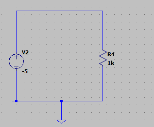
Schematic of a circuit with a voltage source labelled V2 at -5 V in series with resistor R4 at 1k, with the bottom rail connected to ground.

it is same as below
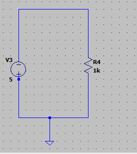
Schematic of a simple circuit: a voltage source labeled V3 with value 5 on the left branch, a resistor R4 rated 1k on the right branch, both returning to a common bottom wire connected to ground.

In the 2nd circuit the 5V is directly shorted with the ground, does it mean the circuit is not correct? Am i missing something? Please advise.
 
As long as the voltage source is floating (like a battery), it can be connected in either polarity.

Many/most DC lab power supplies float the +/- outputs so you can do just that (or stack multiple power supply voltages), and they usually make an Earth Ground connection available as well in case you want to use it.

Front-panel photo of a Korad benchtop DC power supply with red LED displays reading 60.00 V and 2.000 A, indicator lights for OCP, C.C, C.V and LOCK, and voltage and current knobs.

https://eleshop.eu/korad-kd6002d.html
 
The 'ground' for such theoretical questions is just the declaration of the reference level/point.

Since it is the reference, usually it's taken as the 0V. So those drawings declaring the ground at 5V or -5V are not really the best: to have the other (not ground-connected) output of the voltage sources marked as -5V and 5V would be better.
 
  • Like
Likes   Reactions: DaveE and berkeman
Rive said:
The 'ground' for such theoretical questions is just the declaration of the reference level/point.

Since it is the reference, usually it's taken as the 0V. So those drawings declaring the ground at 5V or -5V are not really the best: to have the other (not ground-connected) output of the voltage sources marked as -5V and 5V would be better.
Thank you for reply, i really did not understand, how the circuit will look like with the above changes.
 
In spice, node 0 is always ground, and that reference is needed somewhere, or you can't measure voltages. A voltage source can be created and connected between any two nodes in the circuit.
You can change the circuit polarity by changing the sign of the voltage, or by swapping the connections or nodes.

Try this spice directive (with two text lines) to declare and connect two voltage sources, Vc and Ve.
Vc Vcc 0 +5
Ve Vee 0 -5

That will create two power supply nodes or rails, one Vcc = +5V, the other Vee = -5V.
Any pin or node labelled Vcc or Vee will then be connected to a supply rail.

Try swapping nodes and polarity to confuse readers, or yourself later.
Vc 0 Vcc -5
Ve 0 Vee +5

SPICE schematic with a .tran 1 directive and two voltage source lines: Vc Vcc 0 +5 and Ve Vee 0 -5. Two resistors R1 and R2, each 1k, connect to Vcc at top and a ground symbol at bottom on the left, and Vee on the right.
 
  • Informative
Likes   Reactions: berkeman
I am referring to the below video https://community.nxp.com/t5/Model-...T/Module-4-Space-Vector-Modulation/m-p/737654
I don't understand the Neutral point which he refers at several points starting at time 3.57. Why does he take neutral point? I observe that at the neutral point the voltage will be VDC/2 - VDC/2 = 0V. Is it a concept or need to connect the load as mentioned at the midpoint of the power source. I am sorry if i am asking the same question several times. Please advise.

Just to add i understood the concept of floating power supply from the previous posts, it is important only the difference of voltages. The negative point need not be at 0V or ground voltage.
 
The neutral point is the common terminal at the centre of the star or Y in a three-phase system.
That point could be connected to the neutral wire, which will be close to ground.
 
PhysicsTest said:
I don't understand the Neutral point which he refers at several points starting at time 3.57. Why does he take neutral point? I observe that at the neutral point the voltage will be VDC/2 - VDC/2 = 0V.

One of the reasons is exactly your observation. The usage of the 'neutral' point as a reference in such a three phase system makes things symmetrical from the point of view of the load. Since you expect some sinus-like (symmetrical) waveforms on the load, this makes some calculations a lot easier.

If you discuss that system from the POW of the battery and control electronics, you can still use the negative terminal as Earth (reference).

As far as circuit analysis goes both approach is valid, as long as you don't mix them up.

It is confusing. Always keep your actual reference point in mind.