How to Calculate Torque for a Rotating Rack?

Click For Summary

Discussion Overview

The discussion revolves around calculating the torque required for a rotating rack system, specifically focusing on the moment of inertia, motor specifications, and the impact of various design elements such as mass distribution and gear configurations. Participants explore theoretical and practical aspects of torque calculation, including the effects of friction and acceleration.

Discussion Character

  • Technical explanation
  • Exploratory
  • Debate/contested

Main Points Raised

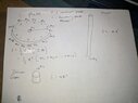
  • Some participants suggest calculating the mass moment of inertia of the turntable to determine the torque needed for acceleration and to account for frictional losses once at speed.
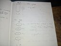
  • There is uncertainty about how to model the rack: whether as a solid cylinder or as individual circular disks, with some proposing treating additional masses as point masses at the maximum radius for a conservative estimate.
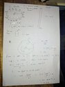
  • Participants discuss the relevance of the driver gear and its moment of inertia in the overall calculations, with some suggesting it should be included while others question its significance.
  • Concerns are raised about the calculated moment of inertia being inconsistent with the expected mass and radius of the system, prompting further scrutiny of the calculations.
  • Some participants mention the importance of understanding frictional losses in the bearings and chain when sizing the motor, noting that the torque required for constant speed may differ from that needed for acceleration.

Areas of Agreement / Disagreement

Participants express differing views on the modeling of the rack and the significance of various components in the torque calculations. There is no consensus on the correct approach to take, and multiple competing perspectives remain throughout the discussion.

Contextual Notes

Participants highlight limitations in the calculations, including assumptions about mass distribution and the need for accurate modeling of frictional losses. There are also unresolved questions about the impact of gear configurations on the overall torque requirements.

Who May Find This Useful

This discussion may be useful for individuals involved in mechanical design, particularly those working on systems requiring precise torque calculations for rotating components, as well as those interested in the practical implications of motor sizing and system dynamics.

Aaron Mac
Messages
26
Reaction score
1
Homework Statement
Smaller sprocket (15 TEETH) is attached to the shaft of the motor and larger sprocket (30 teeth) is attached to the shaft of the rack. I am targeting a speed of 10rpm to 12rpm of the rack. However, i am having trouble sizing the motor for this action.
Relevant Equations
Chain traction force, Shaft power
The weight of the rack is supported on an axial bearing as seen in the attached pdf below. I have made an attempt to calculate the torque by taking a look at the chain traction force and the required shaft power to make the plates rotate. For the moment of inertia case i don't know how to treat this case also and also mass will be distributed at random on the circular plates. Please can someone help me or guide me
 

Attachments

Last edited:
Physics news on Phys.org
10 -12 rpm? Additional mass(s) placed at random places. Is this a rotating cupcake display?
 
  • Like
Likes   Reactions: scottdave and Aaron Mac
Anyhow. To get started, in order to spec a motor you should compute the mass moment of inertia of the turntable. This is relevant for the period of time when the turntable is accelerating from rest to the desired rpm. After acceleration of the system has ceased, the remaining power demand will be frictional losses in bearings and other drive components. In general, you should be basically shooting for a slight overestimate.
 
Last edited:
  • Like
Likes   Reactions: Lnewqban and Aaron Mac
erobz said:
10 -12 rpm? Additional mass(s) placed at random places. Is this a rotating cupcake display?
No haha but could use it!
 
erobz said:
Anyhow. To get started, in order to spec a motor you should compute the moment of inertia of the turntable. this is relevant for the period of time when the turntable is accelerating from rest to the desired rpm. After acceleration of the system has ceased, the remaining power demand will be frictional losses in bearings and other drive components. In general, you should be basically shooting for a slight overestimate.
Yes but how do i treat the rack? As a solid cylinder? Or individual circular disks? That is 4 circular disks? And from there on what shall be calculated to find the torque required?

Have you seen the attached pdf above? Is it relevant?

Kind Regards,
Aaron
 

Attachments

  • d.jpg
    d.jpg
    30.8 KB · Views: 152
Aaron Mac said:
Yes but how do i treat the rack? As a solid cylinder? Or individual circular disks? That is 4 circular disks? And from there on what shall be calculated to find the torque required?

Have you seen the attached pdf above? Is it relevant?

Kind Regards,
Aaron
Treat the vertical posts as point masses at their radius of rotation. The plates as cylinders of radius ##r_{p}##, shaft as a cylinder, gears as a cylinder. Treat each of the randomly placed masses at the furthest radial distance possible (maintaining symmetry - unbalanced thigs tend to wobble) as point masses. That should maximize the moment of inertial, giving you some built in "fudge factor"
 
Last edited:
  • Like
Likes   Reactions: Lnewqban and Aaron Mac
erobz said:
Treat the vertical posts as point masses at their radius of rotation. The plates as cylinders of radius ##r_{p}##, shaft as a cylinder, gears as a cylinder. Treat each of the randomly placed masses at the furthest radial distance possible (maintaining symmetry - unbalanced thigs tend to wobble) as point masses. That should maximize the moment of inertial, giving you some built in "fudge factor"
Thank you for your answer once again. I have attached an image below for the derivation, sorry for the uncleanliness btw. Should i also take into account the driver Gear also?

Let's suppose i get Total Moment of inertia as 100kgm^2. What do i do next?

Thank you for your guide dear friend!
 

Attachments

  • 2e.jpg
    2e.jpg
    23.1 KB · Views: 150
Aaron Mac said:
Should i also take into account the driver Gear also
Yes, just start at the pinion and work your way out from there.

Note, be careful with the gears (they have related but different angular velocities). You are going to have to relate them to the angular acceleration of the table when accounting for their moment of inertia.
Aaron Mac said:
Let's suppose i get Total Moment of inertia as 100kgm^2. What do i do next?
After that you need to determine an acceptable angular acceleration for the application. Just pretend you want the angular acceleration to be constant ( I won't be in reality, but we are just aiming for an upper bound at the moment)... This thing is rotating fairly slowly. Maybe you can accept this turntable taking 2 full rotations to get up to full speed, maybe 4 ? from there what kinematic relationship would you apply to determine ##\alpha##, that involves ##\omega, \theta##?
 
Last edited:
erobz said:
Yes, just start at the pinion and work your way out from there.

Note, be careful with the gears (they have related but different angular velocities). You are going to have to relate them to the angular acceleration of the table when accounting for their moment of inertia.

After that you need to determine an acceptable angular acceleration for the application. Just pretend you want the angular acceleration to be constant ( I won't be in reality, but we are just aiming for an upper bound at the moment)... This thing is rotating fairly slowly. Maybe you can accept this turntable taking 2 full rotations to get up to full speed, maybe 4 ? from there what kinematic relationship would you apply to determine ##\alpha##, that involves ##\omega, \theta##?
I have attached the image please check it if it is right. And also i didn't take into account the driver Gear into consideration when deriving the moment of inertia of the whole system. I suppose it is not important, am i right?
And are the calculations i sent initially for the chain traction force etc, should i still take that into account for the motor sizing?
Thanks in advance
 

Attachments

  • WhatsApp Image 2023-01-15 at 21.30.38.jpg
    WhatsApp Image 2023-01-15 at 21.30.38.jpg
    30.5 KB · Views: 150
  • #10
Aaron Mac said:
...
The weight of the rack is supported on an axial bearing as seen in the attached pdf below.
Welcome, @Aaron Mac !

The PDF file shows diameter of discs as to be 30 mm.
In that case, there is no calculation to make, as any rotational inertia will be very small.

More energy will be consumed by that horizontal 1/4-pitch chain and both sprockets due to gravity induced misalignment.

Would you be able to use a motor with output of 20 to 24 rpm?
 
  • Like
Likes   Reactions: erobz
  • #11
Lnewqban said:
Welcome, @Aaron Mac !

The PDF file shows diameter of discs as to be 30 mm.
In that case, there is no calculation to make, as any rotational inertia will be very small.

More energy will be consumed by that horizontal 1/4-pitch chain and both sprockets due to gravity induced misalignment.

Would you be able to use a motor with output of 20 to 24 rpm?
Hello there, actually the system being built should be able to to stop at 4 positions minimum, you can see on top of the rack i have divided the sections from A to F. But in actual system the discs will be divided into 4, i.e A to D. So i will be using a stepper motor for that. Upon building the prototype and testing it that i will know if 20 to 24 rpm is acceptable. This is why i chose a safer option of 12 rpm which is relatively slow.
And for the gravity induced misalignment, the sprocket on the motor shaft will be fixed with set screws, but i can also use a little shaft collar to prevent that from happening.
And the driven gear can also use a shaft collar and a thrust bearing to minimize the friction between the sprocket and shaft collar. I have made a little freehand sketch to picture what i am trying to say. I don't know if that makes sense, i don't have much experience in this subject i am still a beginner.

But how would you size a motor for that system?
Thank you for your help.
 

Attachments

  • getfwd.jpg
    getfwd.jpg
    13.7 KB · Views: 133
  • #12
A couple of points;

a) To find the torque needed to make the system run at a constant speed, you need to know the frictional losses in the bearings and the chain. This torque could be a lot less than the torque needed to accelerate the system (assuming everything is well lubricated!). So when acceleration is complete, the torque will need to be reduced to keep the speed constant. Or maybe (as suggested by @Lnewqban) you could find a motor which settles at a constant speed.

b) You appear to have calculated the total moment of inertia to be 100 kg m². That can’t be right considering the total mass is only a few kg and the radius is 0.3m!
 
  • Like
Likes   Reactions: Aaron Mac
  • #13
Steve4Physics said:
A couple of points;

a) To find the torque needed to make the system run at a constant speed, you need to know the frictional losses in the bearings and the chain. This torque could be a lot less than the torque needed to accelerate the system (assuming everything is well lubricated!). So when acceleration is complete, the torque will need to be reduced to keep the speed constant. Or maybe (as suggested by @Lnewqban) you could find a motor which settles at a constant speed.

b) You appear to have calculated the total moment of inertia to be 100 kg m². That can’t be right considering the total mass is only a few kg and the radius is 0.3m!
Thank you for your answer, I just took the inertia value at random for as an example. Even when overestimating some parameters the Total moment of inertia doesn't even reach 0.2 kgm^2.
 
  • Like
Likes   Reactions: Steve4Physics

Similar threads

  • · Replies 7 ·
Replies
7
Views
5K
  • · Replies 2 ·
Replies
2
Views
2K
  • · Replies 5 ·
Replies
5
Views
3K
  • · Replies 5 ·
Replies
5
Views
5K
  • · Replies 6 ·
Replies
6
Views
4K
  • · Replies 2 ·
Replies
2
Views
3K
  • · Replies 8 ·
Replies
8
Views
4K
Replies
9
Views
8K
  • · Replies 3 ·
Replies
3
Views
2K
  • · Replies 49 ·
2
Replies
49
Views
4K