How to find maximum load on steel sqare tube

Click For Summary
SUMMARY

This discussion focuses on determining the maximum load capacity of a steel square tube structure with one fixed end and a free-hanging end, measuring 2230 mm in length. The load is applied at the free end, specifically at a distance of 1040 mm from the fixed point. Participants emphasize the importance of understanding the structural configuration, load application, and material properties, while also highlighting safety and liability concerns. The conversation concludes that without adequate details and verification, precise calculations cannot be provided.

PREREQUISITES
  • Understanding of structural engineering principles
  • Knowledge of load calculations and factors of safety
  • Familiarity with steel material properties
  • Experience with structural analysis methods
NEXT STEPS
  • Research methods for calculating maximum load on cantilever beams
  • Study the principles of static equilibrium in structural analysis
  • Learn about the implications of factors of safety in engineering design
  • Explore software tools for structural analysis, such as SAP2000 or ANSYS
USEFUL FOR

Structural engineers, civil engineering students, and professionals involved in designing or analyzing load-bearing structures will benefit from this discussion.

NSNS
Messages
10
Reaction score
0
TL;DR
how to find a maximum load on a steel square tube that has one fixed end to the wall and another end is hanging free
how to find a maximum load on a steel square tube that has one fixed end to the wall and another end is hanging free.
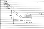
suppose the beam is 2230 mm long and the load is applied on the beam on the free end w= 1040 mm. but there also a steel square tube that welded to the middle of the beam and has a fixed endpoint point to the wall

I can't upload a picture but its look like this III is the area where load will be apply (w), .. is steel square tube. ..
. ..
. .. IIIIIIII
.......
 
Engineering news on Phys.org
What is the purpose of this structure? And can you do any better with the description or upload a photo? It is pretty vague.
 
I just want to know the maximum load of it, maybe with the factor of safety =2
 

Attachments

  • Screenshot (34).png
    Screenshot (34).png
    54.5 KB · Views: 201
We need to know what this is for. What you are asking is not simple, and the structure you've drawn is beefy enough that we have to be concerned with safety and liability issues in discussing it. How the load is applied, how the elements are attached to each other matter and what the wall (?) is made of matter, for example.
 
I have just been asked to find the maximum load of the structure. the section that I draw is the base which will attach with another part. but the load is just the weight of the structure that will be weld to it again.
 
NSNS said:
I have just been asked to find the maximum load of the structure.
Sorry, but that is not sufficient. We cannot answer/publicly discuss this question.
 
I mean it's not HW but at least can you guide me on how to calculate for its, or that least which method should be used to solve this. it's not truss right?
 
we do not suppose to use the truss method right?
 
This thread is locked because we cannot verify the safety of the structure.
 

Similar threads

Replies
3
Views
2K
  • · Replies 2 ·
Replies
2
Views
3K
  • · Replies 5 ·
Replies
5
Views
6K
  • · Replies 12 ·
Replies
12
Views
1K
Replies
6
Views
3K
  • · Replies 4 ·
Replies
4
Views
3K
Replies
11
Views
6K
Replies
9
Views
11K
  • · Replies 1 ·
Replies
1
Views
3K
Replies
2
Views
3K