interpreting TDR properly question

  • Thread starter Thread starter yefj
  • Start date Start date
yefj
Messages
108
Reaction score
2
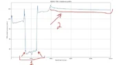
Hello, the following photo represent TDR of differential straight line SDD11.my line is 8 inch BW is 67GHz.
Two questions:
1. I know that artificial ringing is accuring in TDR because we done have infinite BW.
How can I see the need for a window in the TDR and what type to use>

2.as you can see we start with 100 ohm but we end with steady 105 ohm.
what is the logic in that? my vna ports are all 100 ohm differential.
its suppose to end with 100 ohm also.
Thanks.
 

Attachments

  • tdr_plot.webp
    tdr_plot.webp
    11.7 KB · Views: 1
Engineering news on Phys.org
I see no ringing in the plot. If the window you refer to is before the FFT, used for the VNA to TDR processing, then it appears not to be needed.

I don't know how you connect to your line, but it seems to be with a 98Ω line from the analyser. Your line being tested has an impedance of 83Ω. Does it have a glass fibre substrate?

The connections at each end of your line are more inductive than capacitive, that is revealed by the +Z spike at both ends of your line.

I assume you have a 104Ω termination resistor, with lead inductance. The 105Ω tail is due to attenuation of the signal with distance from the analyser.

A picture of your test jig would be useful. I would like to see detail of the connections to your line and the line termination resistor.
 

Similar threads

  • · Replies 4 ·
Replies
4
Views
2K
  • · Replies 8 ·
Replies
8
Views
2K
  • · Replies 11 ·
Replies
11
Views
2K
  • · Replies 20 ·
Replies
20
Views
2K
  • · Replies 21 ·
Replies
21
Views
13K
  • · Replies 52 ·
2
Replies
52
Views
9K
  • · Replies 25 ·
Replies
25
Views
2K
  • · Replies 5 ·
Replies
5
Views
2K
  • · Replies 13 ·
Replies
13
Views
16K
  • · Replies 6 ·
Replies
6
Views
2K