LED module failing due to DC motor?

In summary, the relays are failing because of voltage spikes produced by the motor inductance when it is switched. You should add a bridge rectifier to the circuit to reduce the voltage spikes.
  • #1
Vatech
54
7
TL;DR Summary
A led module gets damaged. Surge Voltage ? Inrush current or am i missing something?
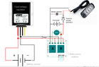
I use a 2 Relay Motor module to control Direction on a motor (linear actuator). When Relay A is active, actuator retracts. When Relay B is active, actuator extents and Led Module is activated. After some repetitions Led module fail.

Cause of the fail?
I believe Surge voltage, although i am not an expert on electronics. Inrush current or instant voltage drop due to high load could also be the reason.
Maybe i am missing something on Relay connection
Please excuse me for the rough presentation, but will help enough to give you a visual perspective of the problem.
Thank you in advance for your suggestions.
1625227247570.png
 
Engineering news on Phys.org
  • #2
My guess is that the LEDs are failing due to voltage spikes produced by the motor inductance when it is switched. Have you installed the 1000 uF capacitor?

Next use a couple of diodes to protect the LED from negative voltages. One diode in parallel across the LED, another in series with the positive lead to the LED.
Select the diode based on the current drawn by the LED module when turned on.
 
  • Like
Likes Vatech
  • #3
Baluncore said:
use a couple of diodes to protect the LED from negative voltages. One diode in parallel across the LED, another in series with the positive lead to the LED.
My impression is that this is an "LED Module", implying that it is a module that drives several LEDs, not individual LEDs that could be protected seperately.

@Vatech -- Any time you drive a relay primary coil, you need to be sure to add a kickback protection diode for when the coil is opened (if it is not already a part of the coil drive circuit).

1625268976548.png

https://www.circuitstoday.com/types-of-relays
 
  • Like
Likes Vatech and hutchphd
  • #4
berkeman said:
My impression is that this is an "LED Module", implying that it is a module that drives several LEDs, not individual LEDs that could be protected seperately.

@Vatech -- Any time you drive a relay primary coil, you need to be sure to add a kickback protection diode for when the coil is opened (if it is not already a part of the coil drive circuit).

View attachment 285373
https://www.circuitstoday.com/types-of-relays

" kickback protection diode" . Could you use my picture to draw the circuit needed? Also, the varistor, do you think that will not be needed? Leds failed after adding the motor (althought they worked for 3-4 times with the motor added)
 
  • #5
We don't see any nameplate info. What is the max current draw of the motor? What is the interrupting rating of the relay?
 
  • #6
Correct, i am sorry, Motor Current 2.5A, Motor Inrush Current <>7.5A. and the relays are gk3ff-12vdc-s-a
 
  • #7
Your relays will momentarily disconnect the motor wire from any connection while it is switching*. The motor inductance will then create a voltage spike if it was previously energized. You should always provide a path for the motor current to flow somewhere.

So, what I would try first is adding 4 fast recovery diodes, 2 on each winding as shown below.

20210703_101332~2.jpg


* some relays will momentarily short all of the contacts together when they switch, but these aren't common, and wouldn't be used in a circuit like this.
 
  • Like
Likes Tom.G, Rive and Vatech
  • #8
I don't believe it is the relay coil causing the problem. It is the motor inductance when a relay switches or the brushes bounce. The two relays make a full bridge. As suggested by @DaveE the voltage spikes could be caught by adding a bridge rectifier to the circuit. The + goes to the positive supply, the – to the negative rail. The AC terminals are connected to the motor terminals.
However the supply rails have inductance also, so they need the 1000 uF capacitor to catch the inductive pulse energy.
Power supplies are not designed to work backwards, holding the output voltage down. There needs to be an over-voltage clamp for the supply rails to protect the LEDs.
 
  • Like
Likes hutchphd and Vatech
  • #9
If i add a 18V varistor between the + and GND line, to be protected by voltage spikes, and a 1000uF on Led line, will not be enough? (The Power source is a 12V battery)
 
  • #10
Vatech said:
If i add a 18V varistor between the + and GND line, to be protected by voltage spikes, and a 1000uF on Led line, will not be enough? (The Power source is a 12V battery)
Maybe, but probably not. Use the clamp diodes, plus a bypass capacitor, as @Baluncore said. They will reliably limit all of the motor voltages to the range -1V to 13V or so, and it is easy to implement.

Varistors are quite sloppy devices and hard to specify. An 18V varistor is a value basically designer to have 18V across it without doing anything; it actually clamps at a significantly higher voltage.
 
  • Like
Likes Vatech, Baluncore and hutchphd
  • #11
DaveE said:
Your relays will momentarily disconnect the motor wire from any connection while it is switching*. The motor inductance will then create a voltage spike if it was previously energized. You should always provide a path for the motor current to flow somewhere.

So, what I would try first is adding 4 fast recovery diodes, 2 on each winding as shown below.

View attachment 285405

* some relays will momentarily short all of the contacts together when they switch, but these aren't common, and wouldn't be used in a circuit like this.
The approach by @DaveE is the most straightforward and likely the most effective to protect both the LEDs AND the relays.

The LEDs are probably being damaged by the reverse voltage from the motor when it turns off (disconnects from the supply). This could be several hundred volts, whereas the reverse voltage rating of LEDs is a few volts.

The suggested configuration will also help protect the relays by diverting the voltage spike to the supply voltage.

Another possible approach is to wire a diode in series with each LED individually, and also wire a diode reversed polarity across each LED; but the approach by DaveE would be simpler.

Cheers,
Tom
 
  • Like
Likes Vatech
  • #12
Tom.G said:
The approach by @DaveE is the most straightforward and likely the most effective to protect both the LEDs AND the relays.

The LEDs are probably being damaged by the reverse voltage from the motor when it turns off (disconnects from the supply). This could be several hundred volts, whereas the reverse voltage rating of LEDs is a few volts.

The suggested configuration will also help protect the relays by diverting the voltage spike to the supply voltage.

Another possible approach is to wire a diode in series with each LED individually, and also wire a diode reversed polarity across each LED; but the approach by DaveE would be simpler.

Cheers,
Tom
I will follow the advice by @DaveE and @Baluncore . If you agree with the connection diagram Please let me know
1) Should i use Tantalum, Ceramic or Electrolytic Capacitor (1000μF)?
2)Do you agree wit the use of TVS diode(transient voltage suppression diode)? and if yes , should i add Unidirectional OR Bidirectional? and is 15V a good selection?
THANK YOU ALL FOR HELPING ME
1625381931827.png
 

Attachments

  • 1625380665749.png
    1625380665749.png
    31.3 KB · Views: 125
Last edited:
  • #13
Vatech said:
I will follow the advice by @DaveE and @Baluncore .
That wasn't our advice. But, sure you can do that. It's not what I would do but it's better than your first version. It will probably work.

Vatech said:
1) Should i use Tantalum, Ceramic or Electrolytic Capacitor (1000μF)?
Electrolytic. 1000uF sounds OK. I would also add a ceramic 0.1uF in parallel with the electrolytic, but you can probably get away with leaving it out.

Vatech said:
2)Do you agree wit the use of TVS diode(transient voltage suppression diode)?
See the first paragraph. TVS diodes are easier to specify than varistors with tighter tolerances. But you will still be clamping at higher voltages than simple clamp diodes back to the supply. The other issue with TVS diodes is that you have to be careful to choose one that can absorb the energy you will put into it during clamping.

Vatech said:
could you suggest one?
If you can't read the datasheets and pick your own, then I'm not sure you should use them at all. Plus, we don't really know about your worst case battery voltages.
Look here: https://www.digikey.com/en/products/filter/tvs-diodes/144?s=N4IgjCBcpg7AzABiqAxlAZgQwDYGcBTAGhAHsoBtcEAXRIAcAXKEASQDtGCBzAgJxABfEmACcADlEoQ6SNnzEylEMjogmLAMqM%2BAS3bchJALQAmabJ0BXReUhUArLWEhjT6DMy5CJO1QBs5iT%2BECTwzi7m9iCMAG54AAQAJrqkSQR4zkA

Anyway, I'd choose a bridge rectifier, not a TVS diode.
 
  • Like
Likes Vatech
  • #14
Deads_LED_circuit.png
 
  • Like
Likes Vatech
  • #15
Dear @DaveE , can a bridge rectifier protect from overvoltageas like the TVS will do?
i found the following TVS diodes available in my country
1625384224581.png

And, should i use Unidirectional TVS or Bidirectional TVS?
Dear @Baluncore , i see you moved the capacitor and added a second Diode in parallel with the TVS diode
This is out of my field, i am not an expert on electronics , but i have to implement a project that involves a lot of electronics. Thats why i was not sure how to connect your suggested schematic between the motor relay and the power line, if @Baluncore you could modify my diagram would be helpful
 
Last edited:
  • #16
I don't trust TVS diodes. When I think it needs one then I could do better by stopping the transients being produced in the first place. The four diodes in the bridge rectifier do just that. They only conduct during transient voltage excursions. Because the high voltage spikes produced by the motor transients are caught by the bridge, the relay contacts will not get burned by the DC arc each time a relay switches off.

The second diode in parallel with the LED module is a cheap investment. It prevents fast negative transients from reaching the LEDs. For negative spikes the parallel diode is duplicating the TVS. The TVS is not essential if the bridge and the 1000 uF are present.
 
  • Like
Likes Tom.G and DaveE
  • #17
Baluncore said:
I don't trust TVS diodes. When I think it needs one then I could do better by stopping the transients being produced in the first place. The four diodes in the bridge rectifier do just that. They only conduct during transient voltage excursions. Because the high voltage spikes produced by the motor transients are caught by the bridge, the relay contacts will not get burned by the DC arc each time a relay switches off.

The second diode in parallel with the LED module is a cheap investment. It prevents fast negative transients from reaching the LEDs. For negative spikes the parallel diode is duplicating the TVS. The TVS is not essential if the bridge and the 1000 uF are present.
Thank you. Then i will not use TVS. Dear @Baluncore & @DaveE , is the folloowing diagramm correct according the use of bridge rectifier?
1625397306033.png
 
  • Like
Likes DaveE
  • #18
That is correct for the bridge.
If you use the bridge you must use the 1000 uF across the motor supply.
 
  • Like
Likes Tom.G and Vatech

1. Why does a DC motor cause LED module failure?

A DC motor can cause LED module failure due to the electrical noise it generates. This noise can interfere with the LED's circuitry and cause it to malfunction or fail.

2. Can this issue be prevented?

Yes, this issue can be prevented by using proper shielding and filtering techniques to reduce the electrical noise generated by the DC motor. Additionally, using high-quality LED modules and properly grounding the circuit can also help prevent failure.

3. How can I tell if my LED module has failed due to a DC motor?

One way to tell if your LED module has failed due to a DC motor is by checking for any visible damage or burn marks on the module. You can also use a multimeter to test the voltage and current output of the module to see if it is within the expected range.

4. Is there a way to fix a failed LED module?

In most cases, a failed LED module cannot be fixed and will need to be replaced. However, if the failure was caused by a DC motor, fixing the motor's electrical noise issue may prevent future failures.

5. Are there any other factors that can contribute to LED module failure?

Yes, there are other factors that can contribute to LED module failure, such as overheating, voltage spikes, and poor quality control during manufacturing. It is important to properly install and maintain LED modules to prevent these issues from occurring.

Similar threads

  • Electrical Engineering
Replies
19
Views
452
Replies
2
Views
988
Replies
12
Views
2K
Replies
5
Views
4K
  • Electrical Engineering
Replies
4
Views
1K
  • Electrical Engineering
Replies
26
Views
4K
  • Electrical Engineering
Replies
5
Views
1K
Replies
11
Views
2K
Replies
1
Views
1K
  • Electrical Engineering
Replies
2
Views
1K
Back
Top