Loop equations for this battery-resistor circuit

AI Thread Summary
The discussion revolves around solving loop equations for a battery-resistor circuit using mesh analysis. Participants clarify that the direction of loops can be chosen arbitrarily, and the equations must be consistent with that choice. The user struggles with solving three equations derived from their loop analysis, specifically for the current I3. They share their equations, which are confirmed to be correct, and seek assistance in solving the resulting system. The conversation emphasizes the importance of understanding mesh analysis and superposition principles to simplify the problem-solving process.
eleking16
Messages
27
Reaction score
5
Homework Statement
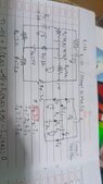
Find the value of current which is flowing through R1 and R8.
Relevant Equations
The First and Second Kirchoff Law for Electricity
1740176554287.jpeg

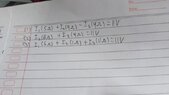
Here's the problem. My teacher said I can determine whatever the loop direction is (Counterclockwise or Clockwise). My problem is with finding the exact value when given 3 equations. Can you help me?

Here's the given loop direction that I used:
Loop 1 (Above): Clockwise
Loop 2 (Left): Counterclockwise
Loop 3 (Right): Clockwise

(This question is in Indonesian, just take the clues from the given question. Please help me, I'm struggling to understand this 3 loop)
 
Physics news on Phys.org
eleking16 said:
My teacher said I can determine whatever the loop direction is (Counterclockwise or Clockwise).
That is true. For each loop you can choose which direction to take as positive and write the equations consistently with that. When you solve the equations, the signs of the results tell you which way it actually flows.
eleking16 said:
My problem is with finding the exact value when given 3 equations. Can you help me?
Please post your equations and attempt at solving them.
 
1740181472354.jpeg
There. You may check the attempt that I have made. I'm just making sure that the loop equations are correct.
 
eleking16 said:
View attachment 357606There. You may check the attempt that I have made. I'm just making sure that the loop equations are correct.
Hello,
Do you have any doubt that you are incorrect in your workings? Please break up the images so we don't have to squint ( maybe that's just me...) at least one for the diagrams one for the math.
 
erobz said:
Hello,
Do you have any doubt that you are incorrect in your workings? Please break up the images so we don't have to squint ( maybe that's just me...) at least one for the diagrams one for the math.
1740189986766.jpeg

1740190216407.jpeg

(Somehow, i can't rotate the pic here. Sorry for the technical difficulty)
 

Attachments

  • 1740190123654.jpeg
    1740190123654.jpeg
    29.5 KB · Views: 25
  • 1740190010204.jpeg
    1740190010204.jpeg
    30.4 KB · Views: 19
erobz said:
Hello,
Do you have any doubt that you are incorrect in your workings? Please break up the images so we don't have to squint ( maybe that's just me...) at least one for the diagrams one for the math.
To answer the question, yes I do. I feel uncertain after determining the loop equations. Im trying to find the value of I3, but kept struggling
 
1740190525666.png


You probably need to rotate it in the viewer before you upload it here.
 
erobz said:
View attachment 357612

You probably need to rotate it in the viewer before you upload it here.
Oh, thanks bro. Appreciate it. Now, can you help me solve it?
If you want the clear picture, go to my first thread.
 
I just spot checked ##\circlearrowright_1##, your equation is coming out correct. I start at the node between ##I_1## and ## I_5## clockwise around the loop element by element:

$$ -5 I _1 + 11 + 4 I_3 -4 + 4 -4I_2 = 0 $$

$$ \implies 5I_1 + 4I_2-4I_3 = 11 $$

So I surmise you understand the branch/loop analysis, even though you're not exactly tackling it the way I am. The branch current direction you assume is to define the polarities across the elements. Then just go around the loop. Thats what I find is the easiest to check over. What was your method for loop 1?

Or do you mean you understand that bit, and are having trouble solving the resulting system of equations?

$$ \boldsymbol X = \begin{bmatrix} I_1\\I_2\\I_3 \end{bmatrix} , \boldsymbol A = \begin{bmatrix} 5&4&-4\\0&[2,8]?&4\\6&1&11 \end{bmatrix} , \boldsymbol B = \begin{bmatrix} 11\\11\\11 \end{bmatrix}$$

You got substitution, Gauss-Jordan elimination, or get a computer ( or A.I. ?) to find ## \boldsymbol X = \boldsymbol A^{(-1)} \cdot \boldsymbol B ## like I did.
 
Last edited:
  • #10
erobz said:
I just spot checked ##\circlearrowright_1##, your equation is coming out correct. I start at the node between ##I_1## and ## I_5## clockwise around the loop element by element:

$$ -5 I _1 + 11 + 4 I_3 -4 + 4 -4I_2 = 0 $$

$$ \implies 5I_1 + 4I_2-4I_3 = 11 $$

So I surmise you understand the branch/loop analysis, even though you're not exactly tackling it the way I am. The branch current direction you assume is to define the polarities across the elements. Then just go around the loop. Thats what I find is the easiest to check over. What was your method for loop 1?

Or do you mean you understand that bit, and are having trouble solving the resulting system of equations?

$$ \boldsymbol X = \begin{bmatrix} I_1\\I_2\\I_3 \end{bmatrix} , \boldsymbol A = \begin{bmatrix} 5&4&-4\\0&[2,8]?&4\\6&1&11 \end{bmatrix} , \boldsymbol B = \begin{bmatrix} 11\\11\\11 \end{bmatrix}$$

You got substitution, Gauss-Jordan elimination, or get a computer ( or A.I. ?) to find ## \boldsymbol X = \boldsymbol A^{(-1)} \cdot \boldsymbol B ## like I did.
My method for loop 1 is actually choosing all of the 3 loops direction, and did a vector comparison with the current which is located at the center (In this case, $$I_2$$ and $$I_3$$ are the center despite $$I_4$$ is also a center, the vector between the second loop and the third loop went into the same direction).

From what I perceived, notice that the current of $$ I_2$$ according to the first and second loop respectively are directing to the same way, to the left. On the other hand, in the first loop,$$ I_3 $$ is moving towards the left while the third loop said it's moving to the right. Since there is an opposing current vector, I put the $$4I_3$$ to be a minus.

Anyway, I just cant solve the resulting system of equations. My equation turns out to be:
(Loop 1): $$ 5I_1 + 4I_2 - 4I_3 = 11 $$
(Loop 2): $$ -6I_1 + 11I_2 + I_3 = 11 $$
(Loop 3): $$ 6I_1 + I_2 + 11I_3 = 11 $$
 
Last edited:
  • #11
Alright, uhm... I actually have sent you the reply, but it's not been sent because it needs the moderator's approval... So, I actually changed the second loop equation because it was wrong. The other 2 loops are correct, tho.


The equation I got was:
Loop 1: $$ 5I_1 + 4I_2 - 4I_3 = 11 $$
Loop 2: $$ -6I_1 + 11I_2 + I_3 = 11 $$
Loop 3: $$ 6I_1 + I_2 + 11I_3 = 11 $$

I did the matrix, and then I got $$286/1176$$ (For the I3)
 
  • #12
eleking16 said:
My method for loop 1 is actually choosing all of the 3 loops direction, and did a vector comparison with the current which is located at the center (In this case, $$I_2$$ and $$I_3$$ are the center despite $$I_4$$ is also a center, the vector between the second loop and the third loop went into the same direction).

From what I perceived, notice that the current of $$ I_2$$ according to the first and second loop respectively are directing to the same way, to the left. On the other hand, in the first loop,$$ I_3 $$ is moving towards the left while the third loop said it's moving to the right. Since there is an opposing current vector, I put the $$4I_3$$ to be a minus.

Anyway, I just cant solve the resulting system of equations. My equation turns out to be:
(Loop 1): $$ 5I_1 + 4I_2 - 4I_3 = 11 $$
(Loop 2): $$ -6I_1 + 11I_2 + I_3 = 11 $$
(Loop 3): $$ 6I_1 + I_2 + 11I_3 = 11 $$
This is loop/mesh analysis you describe. Your diagram ( and the equations that include node equations and branch currents) indicated you were doing a branch-current.

With the mesh approach you need only to define the three loop currents. When loop currents share a branch you add them vectorially (using the associated polarities). Such that for example the branch current you have labeled ##I_1## would be the sum of loop current 1 and loop current 2.


As far as the matrix solution, my computer gives the same result for branch current ##I_3## given your matrices.
 
Last edited:
  • #13
erobz said:
This is loop/mesh analysis you describe. Your diagram ( and the equations that include node equations and branch currents) indicated you were doing a loop/branch.

With the mesh approach you need only to define the three loop currents. When loop currents share a branch you add them vectorially (using the associated polarities). Such that for example the branch current you have labeled ##I_1## would be the sum of loop current 1 and loop current 2.


As far as the matrix solution, my computer gives the same result for branch current ##I_3## given your matrices.
Yep, that's how I was taught to find the value of a current, I suppose...
 
  • #14
eleking16 said:
Yep, that's how I was taught to find the value of a current, I suppose...
So if I were to find the $$I_6$$, is it still possible for me?
 
  • #15
eleking16 said:
So if I were to find the $$I_6$$, is it still possible for me?
Yeah, that segment has no other loop current "meshing" with it. So it is the current of that loop. So it makes ##I_6 = \circlearrowright I_3## (the branch current ##I_6## is the loop current ##I_3##).
 
Last edited:
  • #16
Just to be more clear: Loop/mesh analysis just reduces the number of variables and equation you have to juggle. You get back to the branch currents by superposition of the loop currents you solve for.

Upside: instead of having the all the branch variables and node continuity equations you have less loop variables you need to work with. Downside: you solve for "Loop currents" not "branch currents", so you must remember to superimpose at the end if particular branches share loop currents.
 
  • #17
erobz said:
Just to be more clear: Loop/mesh analysis just reduces the number of variables and equation you have to juggle. You get back to the branch currents by superposition of the loop currents you solve for.

Upside: instead of having the all the branch variables and node continuity equations you have less loop variables you need to work with. Downside: you solve for "Loop currents" not "branch currents", so you must remember to superimpose at the end if particular branches share loop currents.
Hmm... I feel like my method is quite complex. How about your method? Is it quite simple or something? Can you break them down one by one? Because I don't quite understand the words like "Superimpose", " Superposition", etc.
 
  • #18
Superposition is a mathematical property of linear systems. In plain language, the way I understand it is the total effect is the sum of its parts, and the parts don't really care about what each other are doing by themselves. What you say as adding "vectorially" is the superposition principle at work.

The Mesh just pairs down the number of variables in your equations. I wouldn't call it quite simple in comparison but it is likely less algebraic manipulation. Have a look at the wiki on it, no sense in reinventing the wheel.

https://en.wikipedia.org/wiki/Mesh_analysis
 
Last edited:
  • #19
erobz said:
Superposition is a mathematical property of linear systems. In plain language, the way I understand it is the total effect is the sum of its parts, and the parts don't really care about what each other are doing by themselves. What you say as adding "vectorially" is the superposition principle at work.
Oh I see... The word is new, so I guess I'll have to get used to it, haha... Now, are you still typing about your method in order to find the value of $$I_3$$ and $$ I_6 $$?
 
  • #20
I'm just re-directing you to the wiki on it for now. Have a look, and try to solve some simple circuit with a small number of "loops" ( 2-3 loops) and see how it pans out.
 
  • #21
erobz said:
I'm just re-directing you to the wiki on it for now. Have a look, and try to solve some simple circuit with a small number of "loops" ( 2-3 loops) and see how it pans out.
Alright, thanks.
 
  • #22
Something like this circuit is a good one to test, because there are probably six ways to Sunday to solve it and verify methodology.

IMG_2378.jpeg


Obviously just make up whatever values you want.
 
  • #23
erobz said:
I'm just re-directing you to the wiki on it for now. Have a look, and try to solve some simple circuit with a small number of "loops" ( 2-3 loops) and see how it pans out.
Alright, uhhmm.. I'm here again, and... I found no success in understanding how the mesh operation works. So, uhm... Can you guide me? :(
 
  • #24
I believe there is a much easier way because of the symmetry.
First, what would happen if we were to replace the ##\epsilon_1## with a simple wire? What current would flow in ##R_1##? (The symmetry should allow you to say right away.) So what currents would flow in the lower two loops?
Now if, instead, we were to replace all the other voltage sources by plain wires. What would the current be in the top wire?
You now have the currents due to ##\epsilon_1## on the one hand and due to the rest on the other hand. Add 'em up.
 
  • #25
haruspex said:
I believe there is a much easier way because of the symmetry.
First, what would happen if we were to replace the ##\epsilon_1## with a simple wire? What current would flow in ##R_1##? (The symmetry should allow you to say right away.) So what currents would flow in the lower two loops?
Now if, instead, we were to replace all the other voltage sources by plain wires. What would the current be in the top wire?
You now have the currents due to ##\epsilon_1## on the one hand and due to the rest on the other hand. Add 'em up.
Wire? As if in... Just a line? So you are telling me that I need to visualize the whole wire without its voltage source?
 
  • #26
Like... This?
1000324234.jpg
 
  • #27
haruspex said:
I believe there is a much easier way because of the symmetry.
First, what would happen if we were to replace the ##\epsilon_1## with a simple wire? What current would flow in ##R_1##? (The symmetry should allow you to say right away.) So what currents would flow in the lower two loops?
Now if, instead, we were to replace all the other voltage sources by plain wires. What would the current be in the top wire?
You now have the currents due to ##\epsilon_1## on the one hand and due to the rest on the other hand. Add 'em up.
When I apply this, I mean... I had current in R1 to be... Clockwise while the 2nd Loop would be counter clockwise and the 3rd Loop would be clock wise... Is that what you meant or I'm missing some parts here?
 
  • #28
eleking16 said:
Like... This?
View attachment 357655
No, I mean two diagrams, one with only the ##\epsilon_1## source and one with only the others. Where a source is omitted, replace it with wire.
You also need to write in the voltage and resistance values to make the symmetry apparent in the second.
And you can simplify a bit by combining pairs of resistors that are in series.
 
  • #29
haruspex said:
No, I mean two diagrams, one with only the ##\epsilon_1## source and one with only the others. Where a source is omitted, replace it with wire.
You also need to write in the voltage and resistance values to make the symmetry apparent in the second.
And you can simplify a bit by combining pairs of resistors that are in series.
1000324257.jpg

This?
 
  • #30
eleking16 said:
If this is not what you're thinking of, can you draw it for me? Sorry if I keep asking, I'm a new guy, who doesn't know how to do loop circuits since the teacher told us to learn independently
 
  • #31
eleking16 said:
Alright, uhhmm.. I'm here again, and... I found no success in understanding how the mesh operation works. So, uhm... Can you guide me? :(
1740322483899.png


You define a loop currents for each loop that does not enclose another loop ## I_1,I_2##. Then go around the resistive elements and give them polarities based on the loop current direction. Voltage source polarity is fixed. Next apply KVL around a loop. I'll do the loop 1:

$$-I_1 R_1 - I_1 R_2 + I_2 R_2 - V = 0 $$

That is the equation for loop one. Notice that the where the loop currents "mesh" the contributions of voltage drop in resistor 2 are "superimposed"

Now you try loop 2 equation.
 
  • #32
erobz said:
View attachment 357660

You define a loop currents for each loop that does not enclose another loop ## I_1,I_2##. Then go around the resistive elements and give them polarities based on the loop current direction. Voltage source polarity is fixed. Next apply KVL around a loop. I'll do the loop 1:

$$-I_1 R_1 - I_1 R_2 + I_2 R_2 - V = 0 $$

That is the equation for loop one. Notice that the where the loop currents "mesh" the contributions of voltage drop in resistor 2 are "superimposed"

Now you try loop 2 equation.
So it's uhhh...

$$ V - I_2R_2 - I_2R_3 - I_1R_2 = 0 $$
 
  • #33
eleking16 said:
So it's uhhh...

$$ V - I_2R_2 - I_3R_3 - I_3R_2 = 0 $$
It should be involving ##I_1,I_2## there is no loop current ##I_3##. Think about how I got each of the terms in the equation for loop 1. Can you see where they come from?
 
  • #34
erobz said:
It should be involving ##I_1,I_2## there is no loop current ##I_3##.
Like that? I edited my previous message
## V - I_2R_2 - I_2R_3 - I_1R_2 = 0 ##
 
  • #35
eleking16 said:
Like that? I edited my previous message
## V - I_2R_2 - I_2R_3 - I_1R_2 = 0 ##
Very close, but check your signs. Notice the polarities across the resistor in the middle. They are different with respect to the direction of each loop current passing through it.
 
  • #36
Oh wait, hm...
## V - I_2R_2 - I_2R_3 + I_1R_2 = 0 ##
erobz said:
Closer, but check your signs.
 
  • #37
eleking16 said:
Oh wait, hm...
## V - I_2R_2 - I_2R_3 + I_1R_2 = 0 ##
Yes, that's it. So you are left with two equations in two unknowns for loop currents ##I_1,I_2##. you solve, and then realize that where in the circuit ##I_1## and ##I_2## mesh ( the branch containing ##R_2##), the loop currents must be superimposed.
 
  • #38
erobz said:
Yes, that's it. So you are left with two equations in two unknowns for loop currents ##I_1,I_2##
And then, I'm just doing the math... That's it.
How about the 3 loop? Is it the same? I think someone suggested me to break the circuit into 2 parts of circuit. One with e1 and the other with the other components such as e2 until e4. The problem is, from your example, it was given the fixated polar of each voltage source and resistance. But my question doesn't even have the polar sign (for resistance). How do we sort it out?
 
  • #39
eleking16 said:
And then, I'm just doing the math... That's it.
How about the 3 loop? Is it the same? I think someone suggested me to break the circuit into 2 parts of circuit. One with e1 and the other with the other components such as e2 until e4.
Is there some confusion? Thats a different problem.

You said you weren't understanding "Mesh Analysis", so I was giving you a simple example to explore/ understand before you go back to your original problem with the newly learned method.
eleking16 said:
The problem is, from your example, it was given the fixated polar of each voltage source and resistance. But my question doesn't even have the polar sign (for resistance). How do we sort it out?
The voltage drops across a resistor by convention So you imagine the currents going around the loop in the directions you chose for loop currents ( clockwise, counterclockwise ) and assign polarities for resistive elements with that in mind.
 
  • #40
erobz said:
Is there some confusion? Thats a different problem.

You said you weren't understanding "Mesh Analysis", so I was giving you a simple example to explore/ understand before you go back to your original problem with the newly learned method.
Oh, I see. I miscaught the direct intention you gave me. My bad 😭. But, really though... With mesh analysis, I feel like what I need to search is technically much less than what I was taught. Instead of having 6 different currents, I have 3 currents. That's amazing!
 
  • #41
eleking16 said:
Oh, I see. I miscaught the direct intention you gave me. My bad 😭. But, really though... With mesh analysis, I feel like what I need to search is technically much less than what I was taught. Instead of having 6 different currents, I have 3 currents. That's amazing!
Well, just apply with care. Likely less variables to deal with algebraically, but still some thought required. Just don't forget that you directly find "loop currents" - a theoretical construct in this technique. Your question is asking for branch currents, so don't forget to mesh the loop currents if elements share loop currents.
 
Last edited:
  • #42
erobz said:
Well, just apply with care. Less variables to deal with algebraically, but still some thought required.
I'll try to implant this new idea with another 3 loop problem tomorrow morning, and I hope it works! :D
 
  • #43
eleking16 said:
No, both diagrams should have all the wires and resistors. All you need to do is change selected cells to be just a wire (or, equivalently, set their voltages to zero). In one diagram it is ##\epsilon_1##, in the other it is all the others.
In the first of those, identify the symmetry and think about what it implies.
 
  • #44
haruspex said:
No, both diagrams should have all the wires and resistors. All you need to do is change selected cells to be just a wire (or, equivalently, set their voltages to zero). In one diagram it is ##\epsilon_1##, in the other it is all the others.
In the first of those, identify the symmetry and think about what it implies.
Seems like I can't visualize it, can you draw it for me?
 
  • #45
eleking16 said:
Alright, uhm... I actually have sent you the reply, but it's not been sent because it needs the moderator's approval... So, I actually changed the second loop equation because it was wrong. The other 2 loops are correct, tho.


The equation I got was:
Loop 1: $$ 5I_1 + 4I_2 - 4I_3 = 11 $$
Loop 2: $$ -6I_1 + 11I_2 + I_3 = 11 $$
Loop 3: $$ 6I_1 + I_2 + 11I_3 = 11 $$

The problem with both the with both Loop 2 and Loop 3 equations is that ##\mathscr E_2= \mathscr E_3= 3 ## volts and ##\mathscr E_4= 7## volts .

You should have the following.

Loop 2: ##\displaystyle \quad -6I_1 + 11I_2 + I_3 = 10 ##

Loop 3: ##\displaystyle \quad 6I_1 + I_2 + 11I_3 = 10 ##
 
  • #46
SammyS said:
The problem with both the with both Loop 2 and Loop 3 equations is that ##\mathscr E_2= \mathscr E_3= 3 ## volts and ##\mathscr E_4= 7## volts .

You should have the following.

Loop 2: ##\displaystyle \quad -6I_1 + 11I_2 + I_3 = 10 ##

Loop 3: ##\displaystyle \quad 6I_1 + I_2 + 11I_3 = 10 ##
Thanks for the correction, I realized and fixed it after I posted it. Then, I did the math
 
  • #47
Since you have solved it, I'll post my solution.

First, collapse ##R_5, R_6## into one resistance of 6Ω. Likewise 7 and 8.

Just taking the ##\epsilon_1## source, there is a left-right symmetry in that ##R_2=R_3## and ##R_5+R_6=R_7+R_8##. This means there is no current through ##R_4##. This leaves us with ##R_2+R_3## in parallel with ##R_5+R_6+R_7+R_8##, and all of that in series with ##R_1##. We can easily solve that to find the currents due to the ##\epsilon_1## source.

Now dropping the ##\epsilon_1## source and instead including the rest, we can use the symmetry to say that there are equal and opposite currents around the left and right lower loops, with no current through ##R_1##.

Having found the currents due to the various sources we can just sum them in each resistor.
 
  • #48
haruspex said:
Since you have solved it, I'll post my solution.

First, collapse ##R_5, R_6## into one resistance of 6Ω. Likewise 7 and 8.

Just taking the ##\epsilon_1## source, there is a left-right symmetry in that ##R_2=R_3## and ##R_5+R_6=R_7+R_8##. This means there is no current through ##R_4##. This leaves us with ##R_2+R_3## in parallel with ##R_5+R_6+R_7+R_8##, and all of that in series with ##R_1##. We can easily solve that to find the currents due to the ##\epsilon_1## source.

Now dropping the ##\epsilon_1## source and instead including the rest, we can use the symmetry to say that there are equal and opposite currents around the left and right lower loops, with no current through ##R_1##.

Having found the currents due to the various sources we can just sum them in each resistor.
So, I need to;

1. Make the equation from one circuit which only has epsilon_1 as the voltage source while R4 doesn't have any current going through.

2. Make the equation from one circuit which only has R2 until R8, and the remaining epsilons (e2, e3, and e4).

Is that it?
 
  • #49
eleking16 said:
So, I need to;

1. Make the equation from one circuit which only has epsilon_1 as the voltage source while R4 doesn't have any current going through.
Yes, but do you see why ##R_4## would have no current?
eleking16 said:
2. Make the equation from one circuit which only has R2 until R8, and the remaining epsilons (e2, e3, and e4).
Yes, but because of the symmetry you can split it into two identical circuits, just mirror images. One has ##\epsilon_2, \epsilon_4, R_2, R_5, R_6## and a half of ##R_4##, while the other has ##\epsilon_3, \epsilon_4, R_3, R_7, R_8## and the other half of ##R_4##.
When I write that ##R_4## is split into two halves, I mean each will have twice the resistance of##R_4##. This is just the parallel resistors formula applied in reverse.
Note that each copy of ##\epsilon_4## has the same voltage as the original, not halved or doubled. Again, do you see why?
 
Back
Top